Rapid cutter-changing mechanism for multi-cutterhead cutting system

A technology of tool changing mechanism and multiple cutter heads, which is applied in forming/shaping machines, metal processing machinery parts, special forming/shaping machines, etc., which can solve the problems of time-consuming, laborious, low efficiency, and difficulty in changing cutter heads, etc.

Inactive Publication Date: 2013-09-11
盐城飞优科技有限公司
View PDF7 Cites 4 Cited by
  • Summary
  • Abstract
  • Description
  • Claims
  • Application Information

AI Technical Summary

Problems solved by technology

[0002] In the process of woodworking machine tool processing boards, due to the processing of different texture requirements, the cutting tool needs to be replaced frequently. How to quickly replace the cutting head from the cutting spindle will directly affect the working efficiency of the machine tool. There are two common ways to position the cutting spindle of the machine tool. One is The cutting spindle is above the processing plate, and the other is that the cutting spindle is below the processing plate. The spindle is placed on the underside of the plate. The cutting efficiency is higher and the cutting effect will be better, but there is a problem that it is not easy to replace the cutting head. The whole process is time-consuming and labor-intensive, and the efficiency is low. When a spindle is equipped with multiple cutter heads and the position of the cutter head is controllable during the cutting process, the spindle must be placed under the plate.

Method used


Image

  • Rapid cutter-changing mechanism for multi-cutterhead cutting system
  • Rapid cutter-changing mechanism for multi-cutterhead cutting system
  • Rapid cutter-changing mechanism for multi-cutterhead cutting system

Examples


Embodiment Construction

[0016] The present invention will be further described below in conjunction with the accompanying drawings and embodiments.

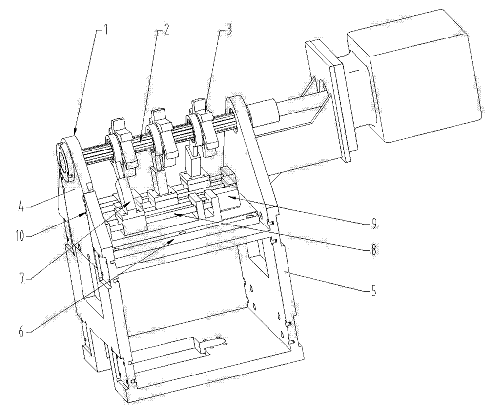
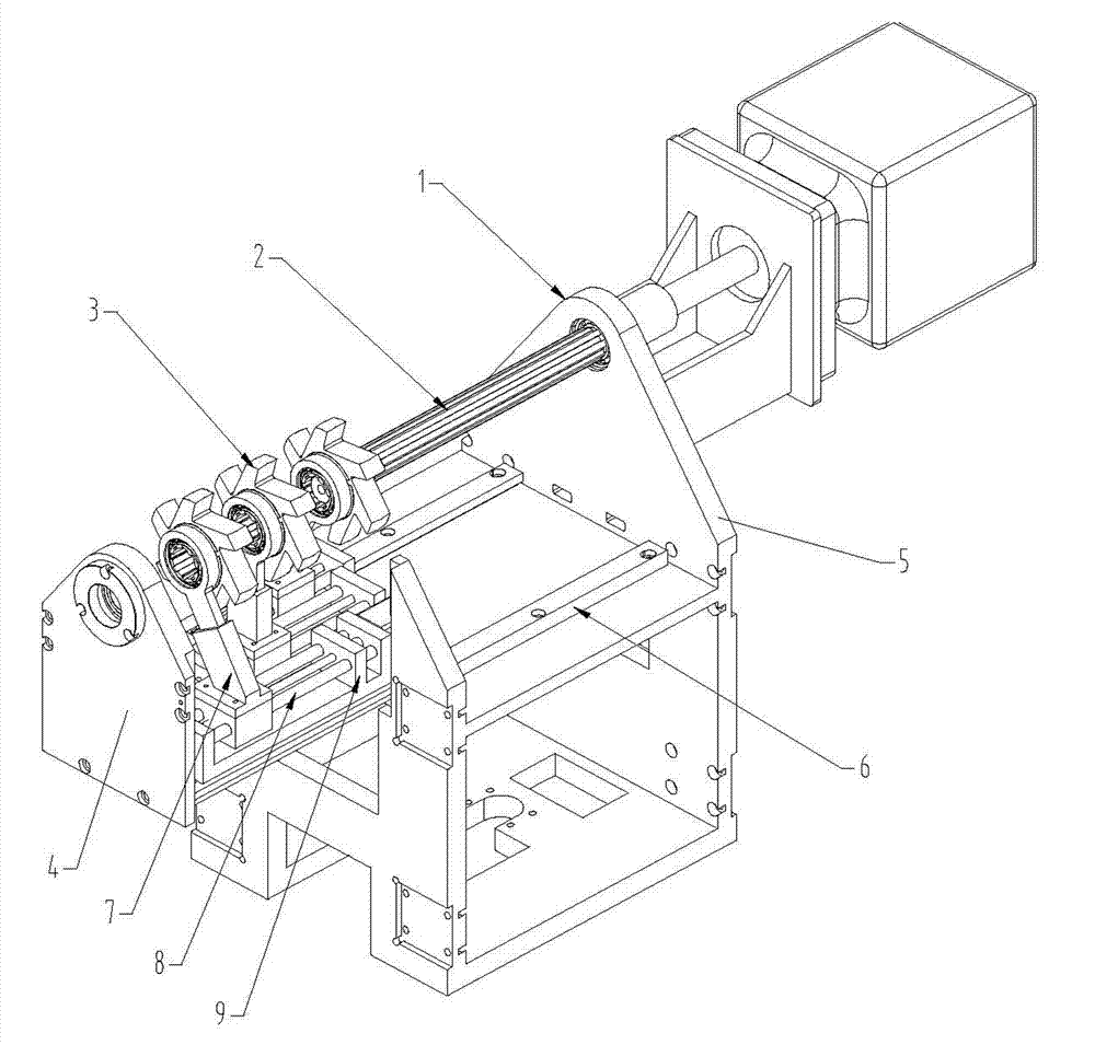
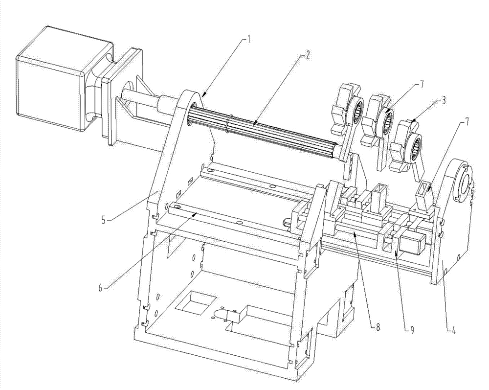
[0017] Such as Figure 1-3 Shown: A quick tool change mechanism for a multi-cutter cutting system, including a spindle support 1, a spindle 2 and a cutter head combination 3, a lever mechanism 7 and a linear guide pair 8, the spindle 2 is installed on the spindle support 1 and the spindle 2 A plurality of cutter head assemblies 3 are installed, and the multi-cutter head co-spindle 2 movable structure design and each cutter head assembly 3 can perform relatively independent axial movement during the cutting process. The upper part of the lever mechanism 7 and its corresponding cutter head The combination 3 is connected and the lower end of the lever mechanism 7 is slidably connected with the linear guide rail pair 8 , and the linear guide rail pair 8 is arranged on the platform of the main shaft support 1 . Wherein the spindle support 1 comprises a mova...


PUM


Abstract

The invention discloses a rapid cutter-changing mechanism for a multi-cutterhead cutting system. The rapid cutter-changing mechanism comprises a main-shaft bracket (1), a main shaft (2), cutter-disk combinations (3), a bar-pulling mechanism (7) and a linear guide rail set (8). The main-shaft bracket (1) comprises a movable bracket (4) and a fixed bracket (5), wherein vertical sections of the movable bracket (4) are L-shaped. Two sliding-rail structures (6) are arranged on a platform of the fixed bracket (5), and the two sliding-rail structures (6) correspond with each other. A horizontal plane of the movable bracket (4) is embedded in the sliding-rail structures (6) and in sliding connection with the sliding-rail structures (6). The vertical end face of the movable bracket (4) is fixedly connected with the vertical end face of the fixed bracket (5). One end of the main shaft (2) is movably arranged in a bearing of the vertical end face of the movable bracket (4), and the other end of the main shaft (2) is arranged in a bearing of the vertical end face of the fixed bracket (5). Through use of the rapid cutter-changing mechanism, rapid replacements can be realized by means of the separated main-shaft bracket, cutter-disk combinations and bar-pulling mechanism, and the rapid cutter-changing mechanism has a compact structure, low cost and a high cutter-changing speed.

Description

technical field [0001] The invention relates to the technical field of woodworking machine tools, in particular to a fast tool changing mechanism for a multi-cutter cutting system with fast tool changing speed, low cost and compact structure. Background technique [0002] In the process of woodworking machine tool processing boards, due to the processing of different texture requirements, the cutting tool needs to be replaced frequently. How to quickly replace the cutting head from the cutting spindle will directly affect the working efficiency of the machine tool. There are two common ways to position the cutting spindle of the machine tool. One is The cutting spindle is above the processing plate, and the other is that the cutting spindle is below the processing plate. The spindle is placed on the underside of the plate. The cutting efficiency is higher and the cutting effect will be better, but there is a problem that it is not easy to replace the cutting head. The whole...

Claims


Application Information

Patent Timeline
Patent Type & Authority Applications(China)
IPC IPC(8): B27C5/00B23Q3/157
Inventor 李青祝张侃楞张侃仓阳程
Owner 盐城飞优科技有限公司
Why Eureka
Try Eureka