Hydraulic type composite vehicle wheel

A hydraulic and hydraulic wheel technology, applied in the direction of wheels, wheel accessories, high elastic wheels, etc., can solve the problems of tire blowout impact resistance, etc., and achieve good shock absorption performance and simple structure

Active Publication Date: 2013-09-11
NANJING UNIV OF AERONAUTICS & ASTRONAUTICS
View PDF10 Cites 12 Cited by
  • Summary
  • Abstract
  • Description
  • Claims
  • Application Information

AI Technical Summary

Problems solved by technology

[0003] In order to solve the problems of tire puncture and puncture and skidding or poor high-speed and impact resistance existing in the existing wheel technology, a hydraulic c...

Method used


Image

  • Hydraulic type composite vehicle wheel

Examples


Embodiment Construction

[0011] Now in conjunction with specific embodiments, the technical solution of the present invention is further described.

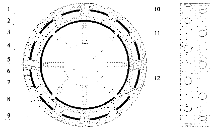
[0012] figure 1 As shown in , the hydraulic composite wheel has inner and outer wheels, the inner wheel is composed of an elastic inner steel ring 3 and an inner rubber layer 2 wrapped outside the elastic inner steel ring 3, and the inner rubber layer 2 has a conical convex The outer ring wheel is composed of the outer steel ring 1 of the wheel and the outer rubber layer 9 wrapped on the outer side of the outer steel ring 1 of the wheel, and the outer ring wheel has a first through-hole structure corresponding to the raised structure 10 of the inner ring wheel 11. At least two rows of protruding structures 10 are arranged in a staggered manner and cooperate with the corresponding first through hole structures 11 so as to improve the off-road performance and limit the relative displacement of the inner and outer ring wheels. The composite wheel is conne...


PUM


Abstract

The invention provides a hydraulic type composite vehicle wheel and belongs to vehicle wheel structures. The hydraulic type composite vehicle wheel is composed of a wheel hub (5), an inner ring vehicle wheel body, an outer ring vehicle wheel body, an inner ring hydraulic wheel arm (8) and an outer ring hydraulic wheel arm (7). The hydraulic type composite vehicle wheel is simple in structure, a hydraulic pump on a vehicle can be used for adding pressure on the hydraulic wheel arms, double working modes can be achieved, high-speed driving can be achieved on a common road face and a road face where slipping can happen easily, and good damping performance is achieved.

Description

technical field [0001] The invention relates to a wheel structure, in particular to a hydraulic composite wheel suitable for both ordinary roads and soft and slippery roads. Background technique [0002] At present, most of the existing vehicle wheels are pneumatic rubber wheels, which are easy to slip on sandy and icy roads, and there are dangerous situations such as tire puncture, air leakage, and blowout, which even endanger the personal safety of the occupants in severe cases. Though some technicians have proposed the conception of some elastic wheels, such as CN200510089076.7, CN201110200238.5 etc., have solved the tyre-puncture problem of rubber wheels, but these wheels still have skidding problem on soft and slippery road surfaces. Simultaneously, some technicians have also proposed the conception of obstacle-crossing wheels, such as CN201110211765.6, CN201110084269.9, etc. The main function of these wheels is to overcome obstacles. and poor impact resistance. Cont...

Claims


Application Information

Patent Timeline
IPC IPC(8): B60B9/28B60B15/00
Inventor 李小龙赵又群刘英杰
Owner NANJING UNIV OF AERONAUTICS & ASTRONAUTICS
Why Eureka
Try Eureka