
Magnetic driving device and valve body structure based on same

A driving device and magnet technology, applied in the driving field, can solve problems such as inability to guarantee the isolation effect, increase the cost of the valve body, and damage the driving source, etc., and achieve the effect of good opening and closing control, long working life and reliable operation

Inactive Publication Date: 2013-09-11
贵友天创(集团)有限公司
View PDF4 Cites 3 Cited by
  • Summary
  • Abstract
  • Description
  • Claims
  • Application Information

AI Technical Summary

Problems solved by technology

In order to separate the directly connected opening and closing parts and the driving source into two different spaces, a tight sealing structure needs to be installed in the valve body structure. This sealing structure increases the cost of the valve body and cannot guarantee a good isolation effect. The sealing structure is damaged during use, and the driving source will be fatally damaged

Method used


Image

  • Magnetic driving device and valve body structure based on same
  • Magnetic driving device and valve body structure based on same
  • Magnetic driving device and valve body structure based on same

Examples


Embodiment Construction

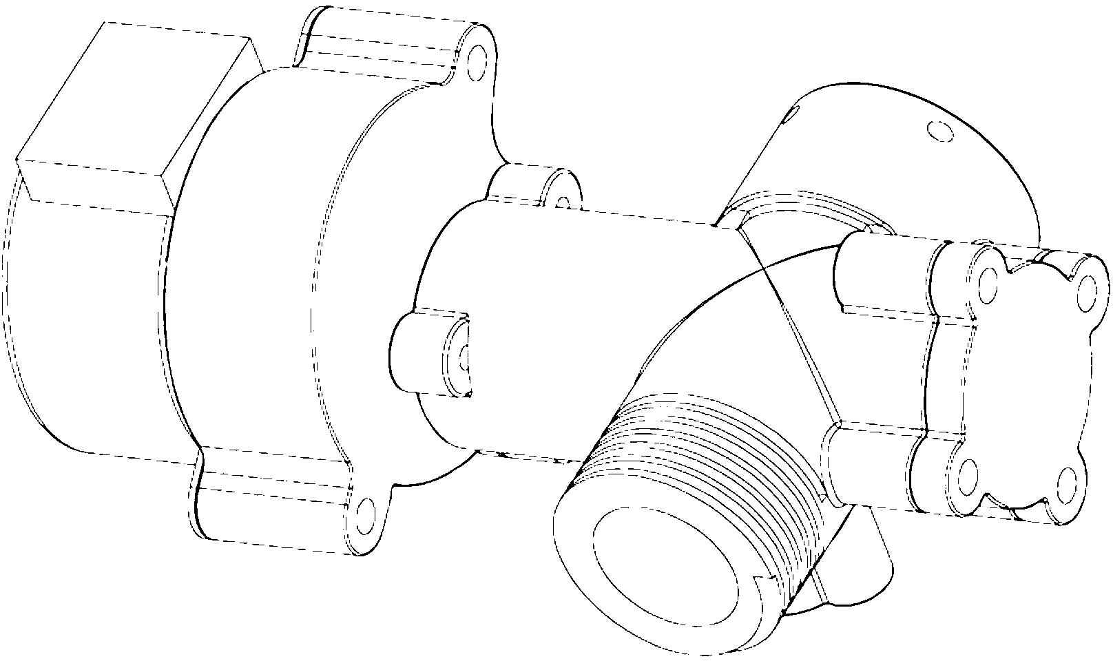
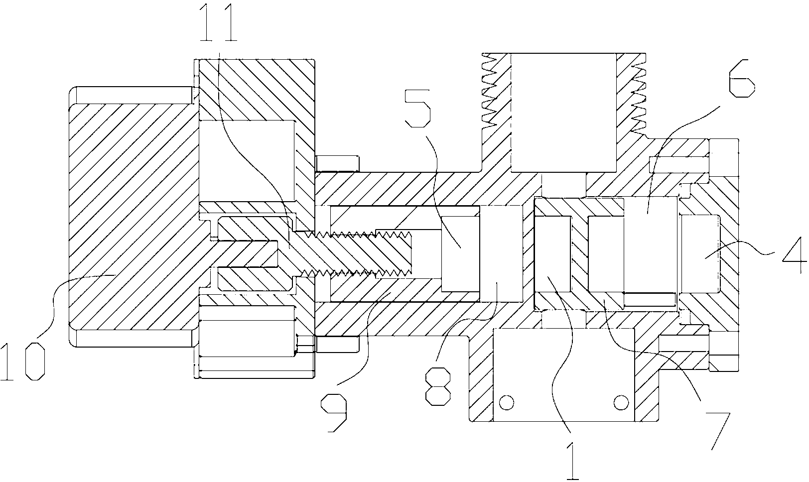
[0022] refer to figure 1 , The magnetic driving device of the present invention includes a first magnet 1, a driven part 2, a sliding guide limiting mechanism 3, a second magnet 4, and a third magnet 5. The first magnet 1 is generally realized by a permanent magnet. The first magnet 1 is fixedly installed on the driven part 2 to form an integral structure with the driven part 2, and the way of fixed installation may be embedding, pasting and the like. The main function of the magnetic driving device is to control the displacement of the driven part 2, so that the driven part 2 can switch various functions with the change of its position. The switching of functions can be realized by the driven part 2 itself. For example, the driven part 2 can be configured as a structural part for opening and closing a channel. When its position changes, the channel can be switched on and off. The valve body structure is based on this application. Function switching can also be realized by u...


PUM


Abstract

The invention discloses a valve body structure, which comprises a first magnet, a driven part, a slide guiding and limiting mechanism, a second magnet and a third magnet, wherein the first magnet is mounted on the driven part, and the second magnet and the third magnet are arranged at two ends, repel with the first magnet and change mutual repelling force between the second magnet and / or the third magnet and the first magnet to control a position of the driven part. The magnetic driving device is reliable in working and long in service life. The valve body structure is ingenious in principle, novel in structure and good in opening and closing control effect and has the advantages of reliability in working and long working life.

Description

technical field [0001] The invention relates to the technical field of driving, in particular to a driving device realized by using magnetic force and a valve body structure based on the driving device. Background technique [0002] Mechanical driving devices are widely used in various equipment and devices. These driving devices can change the state of certain mechanisms to achieve certain specific functions. Displacement control is the most commonly used application field of drive devices. It drives the displacement of certain components to achieve various functions such as switch opening and closing, state switching, and flow control. At present, the driving devices used for displacement control are generally realized by motors and cylinders. These implementation technologies cannot avoid connecting the driven part with the above-mentioned driving source. In order to prevent the driving source from being affected by the working environment of the driven part and cause fa...

Claims


Application Information

Patent Timeline
Patent Type & Authority Applications(China)
IPC IPC(8): F16K31/08F16K3/24
Inventor 吴章杰
Owner 贵友天创(集团)有限公司
Learn More