
Directional propagation antenna housing and directional antenna system

A radome and antenna technology, applied in the field of communication, can solve the problems of no electromagnetic wave directional radiation, single function of the radome, etc., and achieve the effects of easy manufacturing and processing, low cost, and meeting directional requirements.

Active Publication Date: 2013-09-11
KUANG CHI INST OF ADVANCED TECH
View PDF3 Cites 1 Cited by
  • Summary
  • Abstract
  • Description
  • Claims
  • Application Information

AI Technical Summary

Problems solved by technology

[0005] The technical problem to be solved by the present invention is to provide a directional propagation radome and a directional antenna system capable of directional propagation of electromagnetic waves in view of the defects of the existing radome with single function and no directional radiation of electromagnetic waves.

Method used


Image

  • Directional propagation antenna housing and directional antenna system
  • Directional propagation antenna housing and directional antenna system
  • Directional propagation antenna housing and directional antenna system

Examples


Embodiment Construction

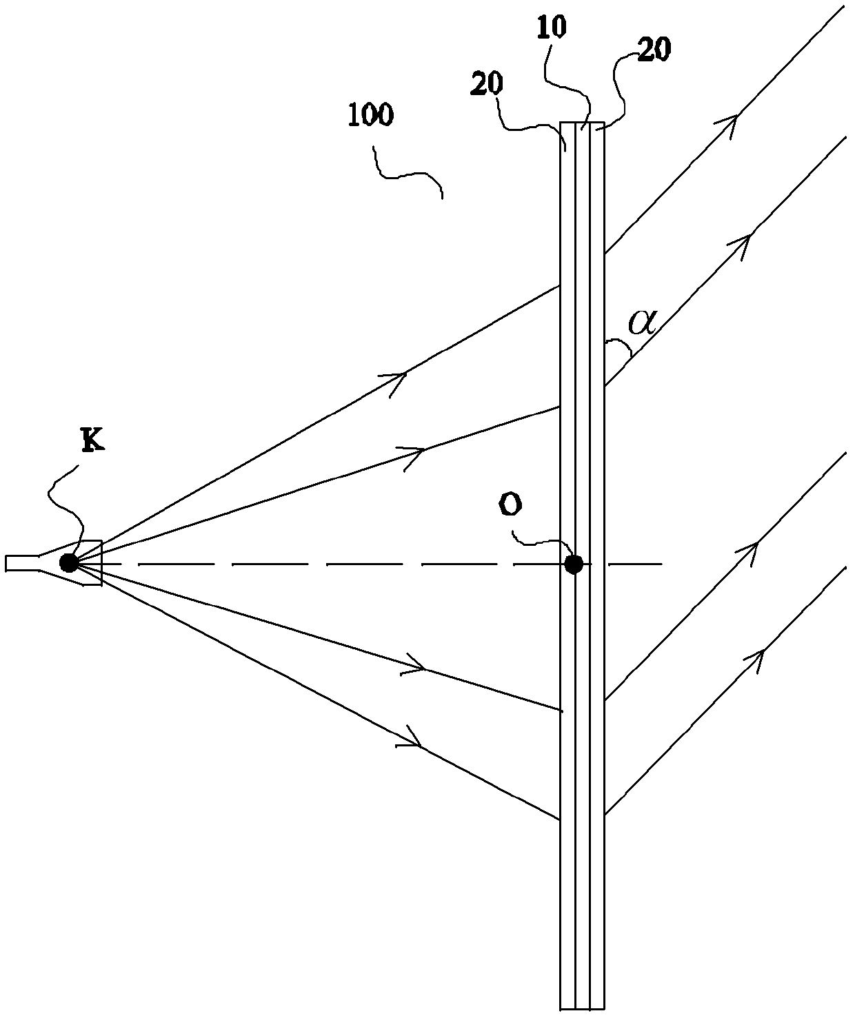
[0047] figure 1 It is a structural schematic diagram of a directional propagation radome according to the first embodiment of the present invention. The directional propagation radome includes a metamaterial panel 100 arranged on the antenna, and the metamaterial panel 100 includes a core layer 10 and a surface on both sides of the core layer 10. Impedance matching layer 20. K is the feed source equivalent point of the antenna, the specific structure of the antenna is not shown, and only the feed source equivalent point K is shown to represent the antenna. Here, the equivalent point K of the feed source is actually the feed point of the antenna (the point where the electromagnetic wave is focused in the feed source or the radiation point of the electromagnetic wave). The projection of the feed equivalent point K on the plane where the front surface of the core layer 10 of the metamaterial panel 100 is located is point O. α represents the angle formed by the electromagnetic w...


PUM


Abstract

The invention discloses a directional propagation antenna housing and a directional antenna system. The directional propagation antenna housing comprises a metamaterial panel arranged on an antenna. The metamaterial panel comprises a core layer, the core layer comprises at least one core layer sheet layer, and each core layer sheet layer comprises a sheet-shaped first substrate and a plurality of man-made microstructures arranged on the first substrate. Through special design, the refraction index distribution of the core layer sheet layers can enable electromagnetic waves emitted by an antenna feed to be capable of forming plane waves exiting at a specific angle after the electromagnetic waves pass through the metamaterial panel. Besides, the overall thickness of the metamaterial panel designed on the basis is on a millimeter level, and the metamaterial panel is very light and thin. Moreover, the refraction index distribution of the core layer can be designed according to different angle requirements to meet different orientation requirements. The antenna housing enables the antenna which does not have the orientation function originally to be capable of achieving directional propagation and meeting the requirement for orientation.

Description

technical field [0001] The present invention relates to the communication field, and more particularly, to a directional propagation radome and a directional antenna system. Background technique [0002] Metamaterials, commonly known as metamaterials, are a new type of synthetic material, which is composed of a substrate made of non-metallic materials and multiple artificial microstructures attached to the surface of the substrate or embedded in the interior of the substrate. The substrate can be virtually divided into multiple substrate units arranged in a rectangular array. Each substrate unit is attached with artificial microstructures to form a metamaterial unit. The entire metamaterial is composed of many such metamaterial units, just like Crystals are composed of countless crystal lattices arranged in a certain way. The artificial microstructures on each metamaterial unit may or may not be identical. Artificial microstructures are planar or three-dimensional structur...

Claims


Application Information

Patent Timeline
Patent Type & Authority Applications(China)
IPC IPC(8): H01Q1/42H01Q19/00
Inventor 刘若鹏赵治亚方小伟杨青王海莲
Owner KUANG CHI INST OF ADVANCED TECH
Learn More