Disc-type plug-in connector

A disc-type card insert and chuck technology, which is applied in the direction of electrical components, computer parts, and connection device parts, etc., can solve the problem of complex structure, large shape of the card insert, and the occupied area of ​​the card insert on the printed wiring board. Larger and other issues, to achieve the effect of simple structure and low cost

Active Publication Date: 2013-09-11
SMK CO LTD
View PDF9 Cites 12 Cited by
  • Summary
  • Abstract
  • Description
  • Claims
  • Application Information

AI Technical Summary

Problems solved by technology

[0010] However, in the disc card insert using the conventional push rod as described above, if the push rod is formed separately from the disc card insert, the chuck cannot be removed from the housing without the push rod or its substitute. It is inconvenient to take it out. If the push rod is set to form an integrated structure with the disc-type card insert, the overall shape of the card insert will become larger, and the area occupied by the card insert on the printed wiring board will become larger. hinder the miniaturization of electronic equipment
[0011] Also, in the case of the above-mentioned push-in / pull-out mechanism, due to the structure of a heart-shaped cam, etc., the overall shape of the card insert becomes larger, and the area occupied by the card insert on the printed wiring board becomes larger, which may hinder the electronics. Equipment miniaturization, and there is a problem of cost increase due to the large number of parts and complicated structure

Method used


Image

  • Disc-type plug-in connector
  • Disc-type plug-in connector
  • Disc-type plug-in connector

Examples


Embodiment Construction

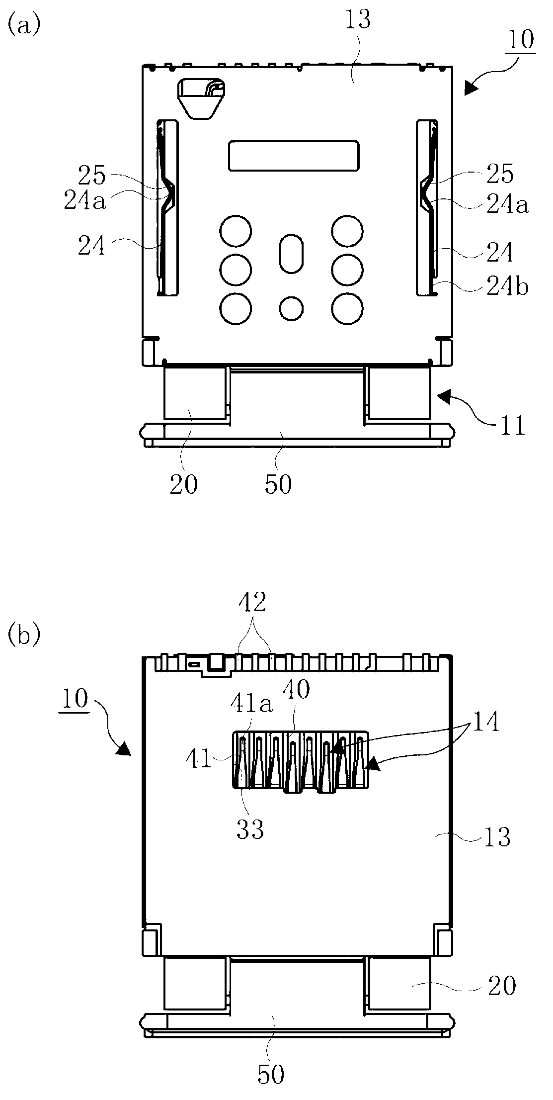
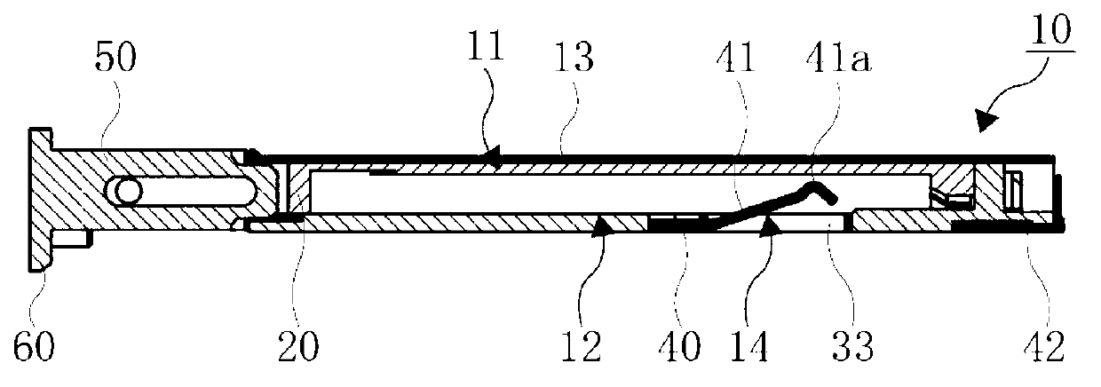
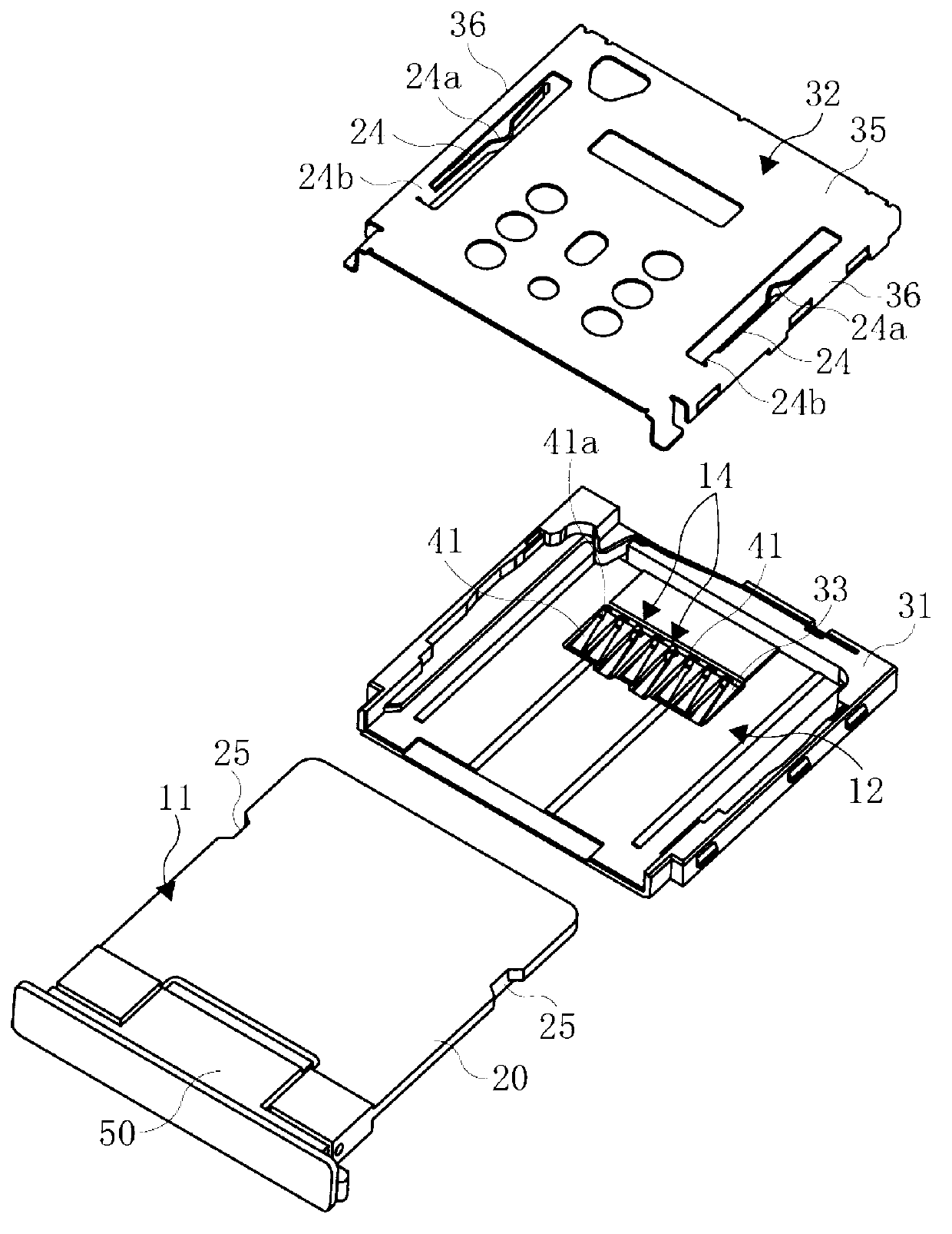
[0087] Below, refer to Figure 1 to Figure 8 The shown embodiment illustrates the actual form of the disk card insert related to the present invention. In the following embodiments, although various limitations are made to the constituent elements, types, combinations, shapes, relative arrangements, etc., these are only For example, the present invention is not limited thereto.

[0088] Symbol 10 among the figure is a disc card plug-in, and symbol A is a memory card such as a flash memory card.

[0089] The disc card inserter 10 includes a chuck 11 for accommodating a memory card A, a case 13 having a disc insertion portion 12 inserted into the chuck 11, and a housing 13 protruding into the disc insertion portion 12 for the memory card A accommodated in the chuck 11. A plurality of contact points 14 contacted by the signal terminals a1, a1, ... make the memory card A accommodated in the chuck 11, and in this state, insert the chuck 11 into the disk insertion part 12 to make t...


PUM


Abstract

The invention relates to a disc-type plug-in connector. The objective of the invention is to provide the disc-type plug-in connector which requires no push rod for pulling or other parts and is capable of pulling out a clamping disc out of a shell through a simple structure. In the disc-type plug-in connector (10), the clamping disc (11) comprises a disc body (20) accommodating a memory card (A), a sliding handle knob (50) connected with the end part at the disc pulling-out side of the disc body (2) in a manner that the handle knob can be pulled out, and a transmission mechanism used for transmitting a force applied on the disc pulling-out direction of the sliding handle knob (50) to the disc body (20) at a specified pulling-out position. The clamping disc (11) can be pulled out from the shell (13) by virtue of grabbing the sliding handle knob (50) pulled out to the specified pulling-out position.

Description

[0001] technology area [0002] The present invention relates to a card connector for electrically connecting a memory card such as an IC card or a flash memory card to a printed wiring board mounted on an electronic device such as a mobile phone or a smart phone. Background technique [0003] Conventionally, memory cards such as IC cards and flash memory cards have been used as external storage media for electronic devices such as mobile phones and smartphones, and the memory cards and printed wiring boards mounted on the electronic devices are electrically connected through card sockets. [0004] In such a card insert, a cartridge including a memory card that can be accommodated, a housing having a disk insertion portion inserted into the cartridge, and a plurality of contact points that protrude into the disk insertion portion and come into contact with signal terminals of the memory card accommodated in the cartridge are used. , and a disc-type card inserter for a take-out...

Claims


Application Information

Patent Timeline
Patent Type & Authority Applications(China)
IPC IPC(8): H01R13/629H01R12/71G06K13/08
Inventor 江尻孝一郎
Owner SMK CO LTD
Why Eureka
Try Eureka