LED lighting device and method for controlling light attenuation thereof

A technology of LED lighting and LED light-emitting tube, applied in the field of lighting, can solve the problem of shortening the service life of LED lighting devices, and achieve the effect of prolonging the service life

Inactive Publication Date: 2016-03-02
BEIJING ITSYNC TECH
View PDF5 Cites 0 Cited by
  • Summary
  • Abstract
  • Description
  • Claims
  • Application Information

AI Technical Summary

Problems solved by technology

[0004] In view of this, the main purpose of the present invention is to provide an LED lighting device and its light decay control method, which can solve the problem in the prior art that the service life of the LED lighting device is shortened due to LED light decay

Method used


Image

  • LED lighting device and method for controlling light attenuation thereof
  • LED lighting device and method for controlling light attenuation thereof
  • LED lighting device and method for controlling light attenuation thereof

Examples


Embodiment 1

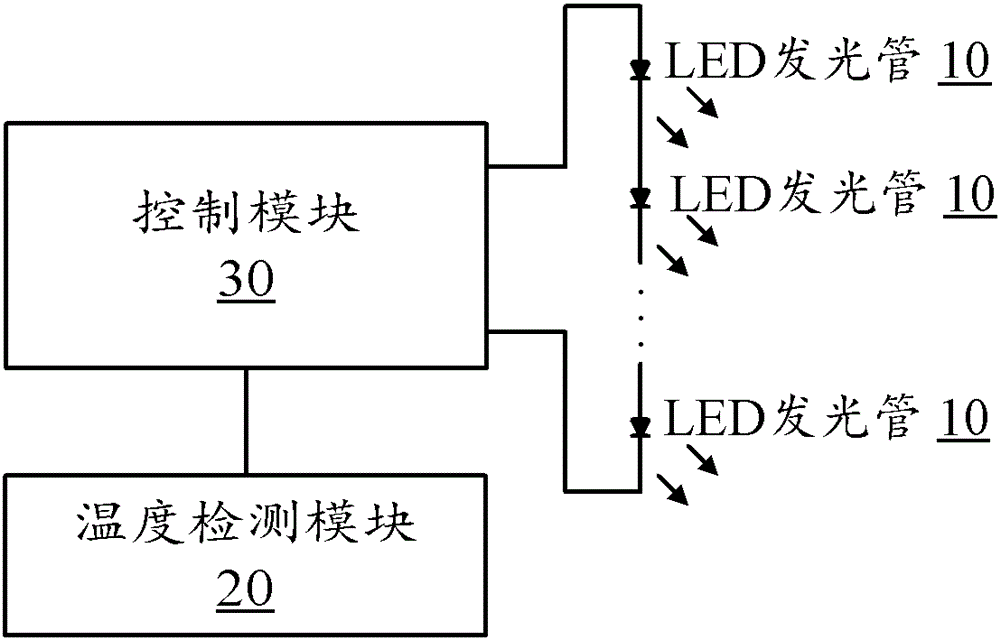
[0017] figure 1 A schematic structural diagram of an LED lighting device according to Embodiment 1 of the present invention is shown, including: at least one LED light-emitting tube 10, a temperature detection module 20, and a control module 30, wherein:

[0018] The temperature detection module 20 is used to detect the temperature in the LED lighting device;

[0019] The control module 30 is configured to adjust the power of at least one LED light emitting tube 10 according to the temperature detected by the temperature detection module 20, so as to control the light decay of the LED lighting device.

[0020] In actual application, the temperature detection module is preferably arranged at a position relatively close to the LED light-emitting tube, so that the detected temperature caused by the heat generated by the LED itself during operation is relatively accurate.

[0021] Generally speaking, the higher the temperature of the environment in which the LED lighting device i...

Embodiment 2

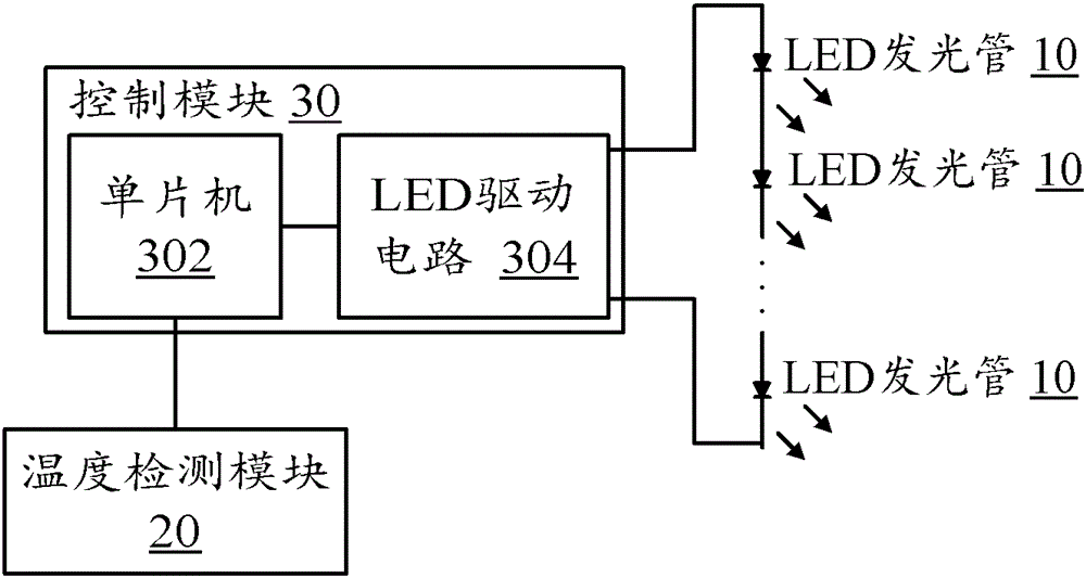
[0023] Such as figure 2 As shown, the control module 30 in Embodiment 1 may further include: a single-chip microcomputer 302 and an LED driving circuit 304, wherein:

[0024] The single-chip microcomputer 302 is used to compare the current temperature T inside the lighting device detected by the temperature detection module 20 with the preset nominal temperature T 标 The size of the internal current temperature T is greater than the nominal temperature T 标 , the power of at least one LED light emitting tube 10 is reduced through the LED driving circuit 304 .

[0025] By presetting a nominal temperature T 标 , when it is detected that the current temperature T inside the LED lighting device is greater than T 标 When it is considered that the internal temperature is too high, it will actively reduce the power of the LED light-emitting tube to reduce the calorific value of the LED light-emitting tube and control the light decay. Therefore, the derating method is adopted in the ...

Embodiment 3

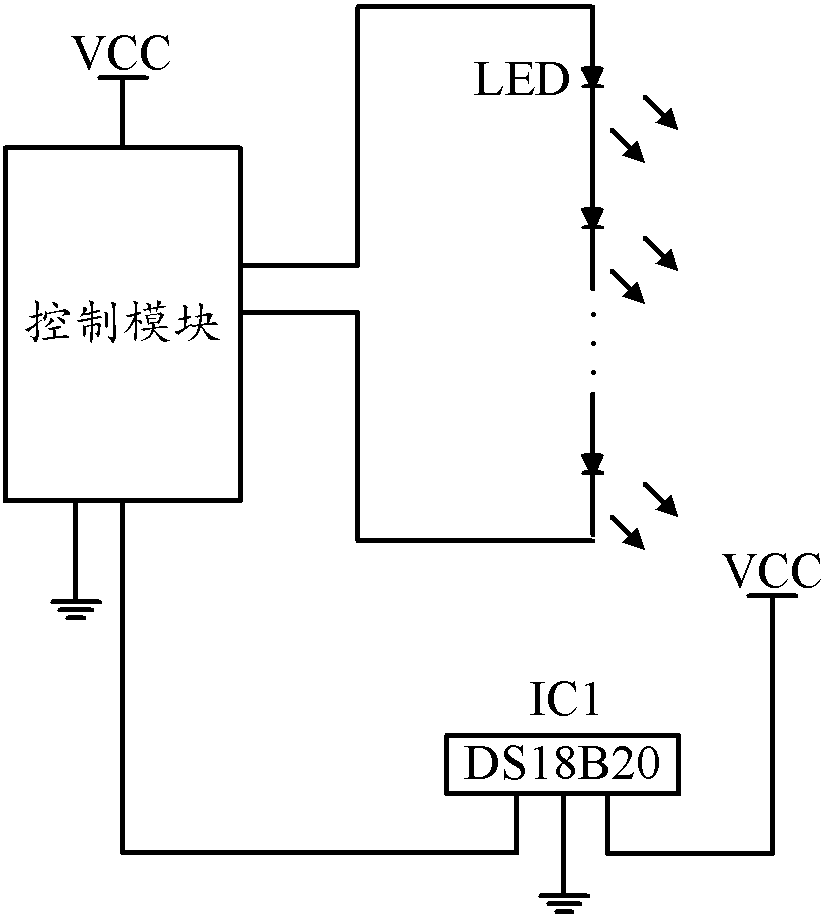
[0033] Such as image 3 As shown, the temperature detection module in Embodiments 1 and 2 can be a single-wire temperature sensor, such as a single-wire temperature sensor with a model number of DS18B20 ( image 3 Indicated by IC1), which is mainly used to detect the temperature change inside the LED lighting device. Other types of temperature sensors can also be selected as required, which is not limited in the present invention. The control module includes a single-chip microcomputer and an adjustable brightness LED driving circuit.

[0034] DS18B20IC1 transmits the detected temperature to the single-chip microcomputer in the control module through the bus between the control module, and the single-chip microcomputer can start the following process according to a certain time interval:

[0035] Step 1: Calculate the detected internal current temperature T and the nominal temperature T 标 The difference ΔT, store ΔT in the temperature difference register;

[0036] Step 2: ...


PUM


Abstract

The invention discloses an LED illuminating device and a light failure control method of the LED illuminating device. The LED illuminating device comprises at least one LED luminescent tube, a temperature detecting module and a control module, wherein the temperature detecting module is used for detecting the temperature in the LED illuminating device, and the control module is used for adjusting the power of the at least one LED luminescent tube according to the temperature detected by the temperature detecting module so as to control the light failure of the LED illuminating device. The LED illuminating device and the light failure control method of the LED illuminating device achieve the effects of controlling the light failure of the LED luminescent tube and prolonging the service life of the LED illuminating device.

Description

technical field [0001] The present invention relates to the technical field of lighting, and more specifically, to an LED lighting device and a light attenuation control method thereof. Background technique [0002] In recent years, with the promotion of energy-saving technology, energy-saving lighting design has become the focus of research in the field of lighting fixtures. Because of its high luminous efficiency, good energy-saving effect, and environmental protection, LED has attracted people's attention in energy-saving lighting design. It is a development trend in today's lighting technology field to use LEDs as lighting lamps to replace traditional lighting lamps. [0003] However, it is well known that when LEDs are used, there will be a certain light decay. LED light decay means that after the LED is lit for a period of time, its brightness will be lower than the original brightness, and the lower part is the light decay of the LED. This kind of light decay will ...

Claims


Application Information

Patent Timeline
Patent Type & Authority Patents(China)
IPC IPC(8): H05B37/02
Inventor 黄喜荣
Owner BEIJING ITSYNC TECH
Why Eureka
Try Eureka