Wig clip

A technology for wigs and clips, which is applied in the field of clips for wigs, can solve problems such as insufficient clamping force, and achieve the effects of improved quality of life, good operability, and smooth opening

Inactive Publication Date: 2013-09-18
SVENSON
View PDF7 Cites 1 Cited by
  • Summary
  • Abstract
  • Description
  • Claims
  • Application Information

AI Technical Summary

Problems solved by technology

[0004] The clamping force of these proposals is not sufficient, and the development of a stable clip for wigs that does not use metal is required

Method used


Image

  • Wig clip
  • Wig clip
  • Wig clip

Examples


Embodiment Construction

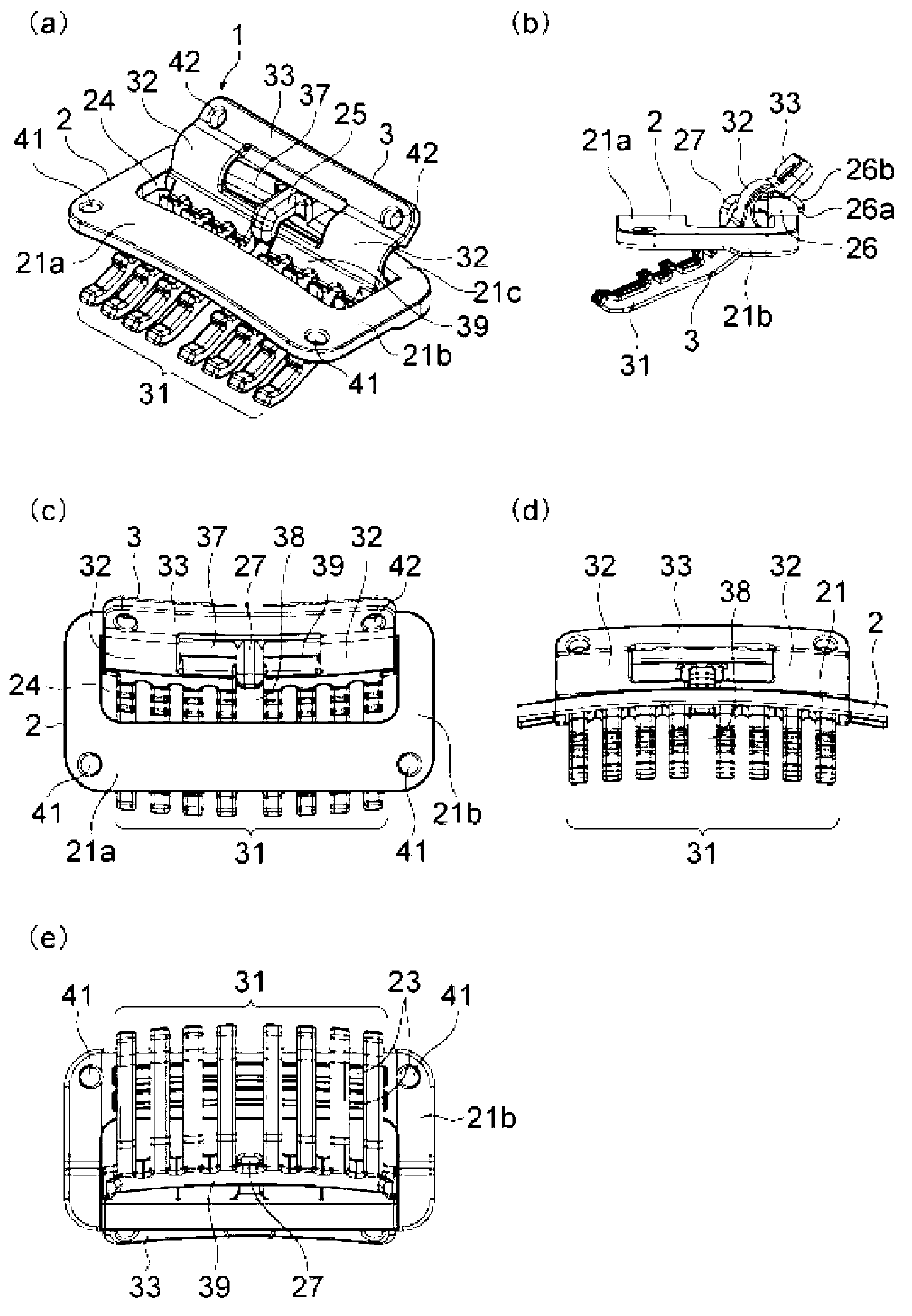
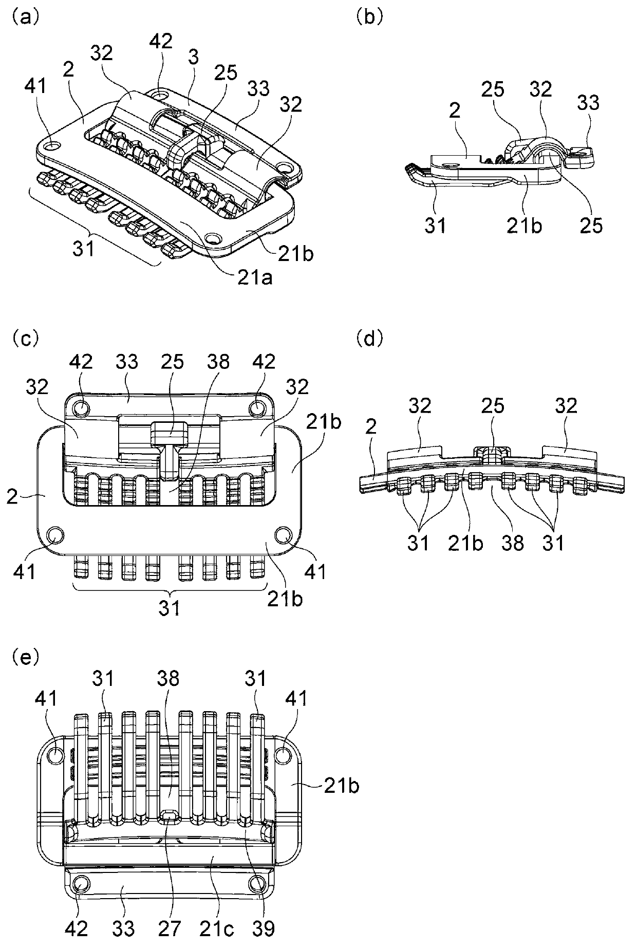
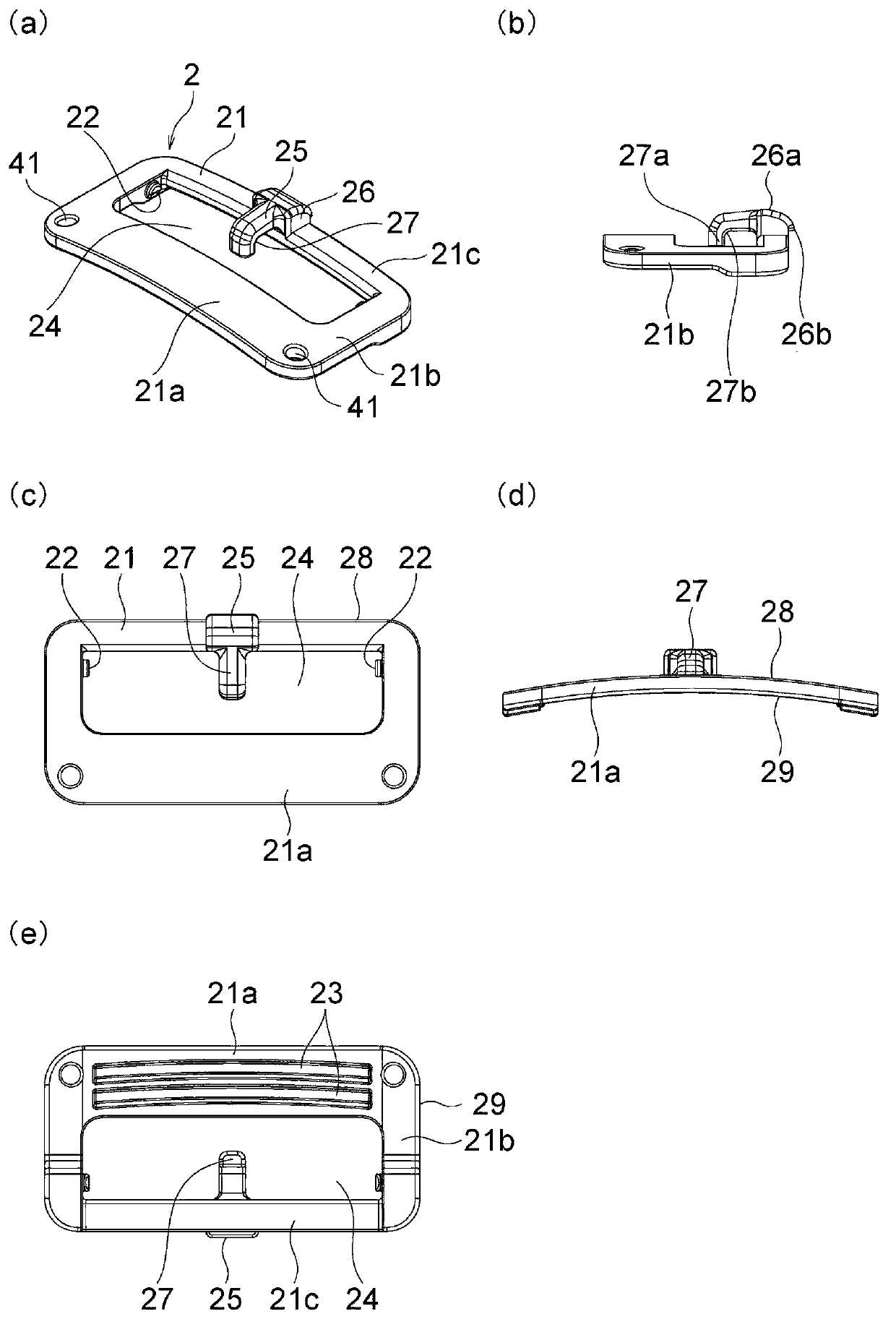
[0053]The clip for a wig of the present invention is a clip for a plastic wig. A clip for a wig is formed by combining a base frame composed of a square frame and a comb body pivotally connected to the base frame. Equipped with a locking mechanism that fixes the posture while the base frame and the comb body are in close contact. The wig can be worn on the head by installing clips for the wig on the wig, etc., putting the wig on the head, sandwiching your own hair between the base frame and the comb body, and locking it in a tight position. department.

[0054] The side frames of the base frame formed by the front, rear, left, and right frames are pivotally connected with the base located in the middle of the comb body. The comb tooth body has a plurality of comb teeth at the front of the base, and has a handle at the rear through the bent spring. The shaft-connected comb body has the following structure, the top of the comb teeth is in contact with the bottom of the front ...


PUM


Abstract

A wig clip constituted by a plastic base frame and plastic comb body, wherein such wig clip is characterized in that: the base frame has pins or holes provided on / in the side elements of a rectangular frame member comprising front / rear elements and side elements; the comb body has multiple comb teeth provided at the front of the base, while a tab is provided at the rear of the base via a spring having a void, with holes or pins formed in / on the left side and right side of the base; and the comb body and base frame are axially joined in a rotatable manner and have such relationship that the tab can be engaged with the lock member, so that the positions of the two can be changed between an open state and clipping state.

Description

technical field [0001] The present invention relates to a clip for a wig used for wearing a wig on the head. Background technique [0002] Usually metal clips are used. Utilize the clip of following structure as the clip for wig, bend and connect the metal thin plate that forms roughly with U shape, set: the plate frame shape base frame that can be bent and reversed; By reversing the bending, the separation and tightness of the comb body and the base frame can be changed. For example, Patent Document 1 (Japanese Patent Laid-Open No. 11-1811) and Patent Document 2 (Japanese Patent Laid-Open No. 2006-37278 ) can be illustrated. exist Figure 7 A conventional example is shown in , and the clip 110 for a wig is configured as follows, and the metal leaf spring 118 and the comb body 115 provided with the metal comb teeth 114 are bent at the buttonhole 116 and assembled in a flexural manner. By reversing the clip for a wig in the direction of the arrow b shown in (c), the comb t...

Claims


Application Information

Patent Timeline
IPC IPC(8): A41G3/00
CPCA41G3/0033A41G5/0073A45D8/22A41G3/00A41G5/00
Inventor 长友孝裕贺曾利进一松岛由太郎
Owner SVENSON
Why Eureka
Try Eureka