
Dog clutch for automated transmission

A technology for tooth clutches and automatic transmissions, applied in mechanical drive clutches, intermeshing clutches, clutches, etc., to solve problems such as prolonged shifting time

Inactive Publication Date: 2013-09-18
AISIN SEIKI KK
View PDF6 Cites 6 Cited by
  • Summary
  • Abstract
  • Description
  • Claims
  • Application Information

AI Technical Summary

Problems solved by technology

Thus, the shift time based on the operat

Method used


Image

  • Dog clutch for automated transmission
  • Dog clutch for automated transmission
  • Dog clutch for automated transmission

Examples


Embodiment Construction

[0041] Hereinafter, a first embodiment of a dog clutch for an automatic transmission mounted to a vehicle will be described with reference to the drawings.

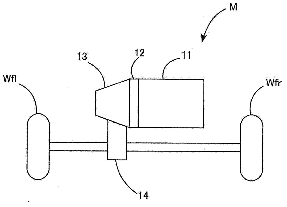
[0042] Such as figure 1 As shown, the vehicle M includes an engine 11, a clutch 12, an automatic transmission (for example, an automatic manual transmission) 13, a differential gear device 14 and driving wheels, specifically a left front driving wheel Wfl and a right front driving wheel Wfr. The engine 11 generates driving force by burning fuel. The engine 11 is configured to transmit driving force to the left front drive wheel Wfl and the right front drive wheel Wfr via the clutch 12, the automatic transmission 13, and the differential gear device 14. That is, the vehicle M is a front-wheel drive vehicle.

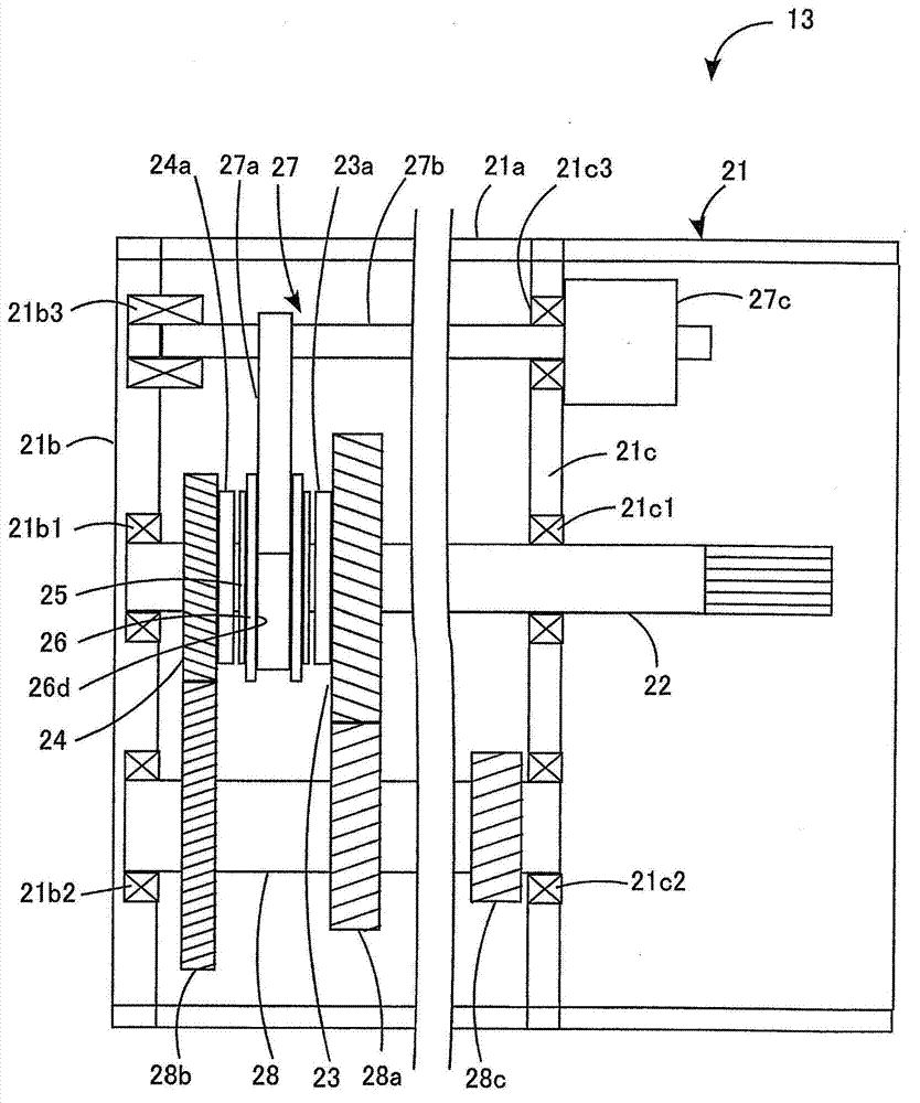
[0043] The clutch 12 is configured to be automatically connected or disconnected based on instructions from the control device. The automatic transmission 13 includes a dog clutch mechanism to automatically select, for e...


PUM


Abstract

A dog clutch for an automated transmission (13) includes a rotary shaft (22) rotatably connecting to one of an input shaft (22) and an output shaft (28) of the automated transmission (13), a clutch ring (23, 24) rotatably supported by the rotary shaft (22) and rotatably connecting to the other of the input shaft (22) and the output shaft (28), a clutch hub (25) fixed to the rotary shaft (22), a sleeve (26) including first teeth (26a1) and second teeth (26b1), an axial driving device (27) moving the sleeve (26), and a dog clutch portion (23a, 24a) arranged at the clutch ring (23, 24), the dog clutch portion (23a) including: clutch forward teeth (23b1) each having an engagement portion (23b4) contactable with each of the first teeth (26a1), and inclined surfaces (23b2) extending from the engagement portion (23b4) toward both sides in a circumferential direction and inclined toward a rear end position (Pe) of the dog clutch portion (23a); and a clutch rearward tooth portion engageable with the second teeth (26b1) and including clutch rearward teeth (23c1).

Description

Technical field [0001] The present invention generally relates to a dog clutch applied to an automatic transmission of a vehicle. Background technique [0002] Patent JP2010-96190A (hereinafter referred to as reference 1) discloses a known tooth clutch device, which includes a rotating shaft, a hub (clutch hub), a sleeve, and a clutch ring. The dog clutch device is configured in a manner described below to achieve high engagement and reduce backlash. The sleeve is slidably engaged with the clutch hub in the axial direction of the rotating shaft. The spline of the sleeve can be engaged with the toothed clutch portion of the clutch ring rotatably arranged with respect to the clutch hub. The spline of the sleeve includes a first tooth and a second tooth. The length (overall depth) of each first tooth in the radial direction of the sleeve is designed to be longer (larger) than the length (overall depth) of each second tooth in the radial direction. Hereinafter, the first teeth an...

Claims


Application Information

Patent Timeline
IPC IPC(8): F16D11/00
CPCF16D11/10F16D2011/002F16D2011/008
Inventor 森匡辅岩崎靖久原田新也
Owner AISIN SEIKI KK
Features
  • Generate Ideas
  • Intellectual Property
  • Life Sciences
  • Materials
  • Tech Scout
  • Unparalleled Data Quality
  • Higher Quality Content
  • 60% Fewer Hallucinations
Learn More