Pressure relief device

A technology of pressure relief device and air relief hole, which is applied to valve devices, safety valves, engine components, etc., can solve the problems of increasing equipment cost, redundant structure, and unfavorable production and development of enterprises, so as to meet pressure relief requirements and realize automatic adjustment. The effect of pressure and promotion of production development

Inactive Publication Date: 2013-09-18
SUZHOU MAIDER MACHINERY
View PDF0 Cites 1 Cited by
  • Summary
  • Abstract
  • Description
  • Claims
  • Application Information

AI Technical Summary

Problems solved by technology

[0002] The pressure relief devices currently used in the market are complex in structure and high in manufacturing cost. They are used in some equipment that does not have strict pressure relief requirements, which will cause redundant structures and redundant functions, which will increase equipment The cost of use is not conducive to the production and development of enterprises

Method used


Image

  • Pressure relief device
  • Pressure relief device

Examples


Embodiment Construction

[0013] The present invention is described below in conjunction with accompanying drawing.

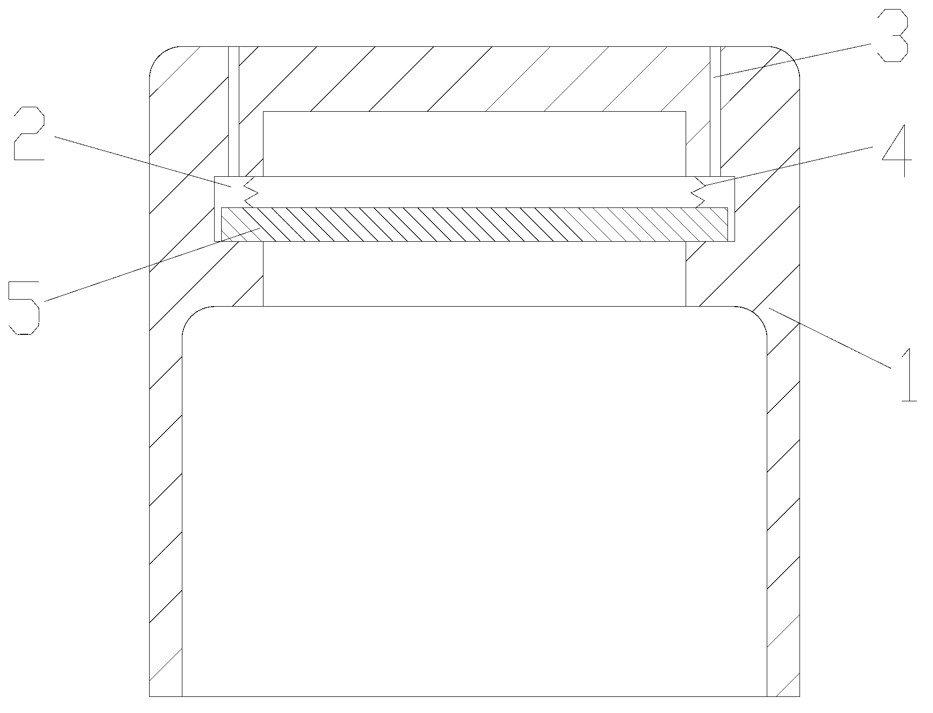
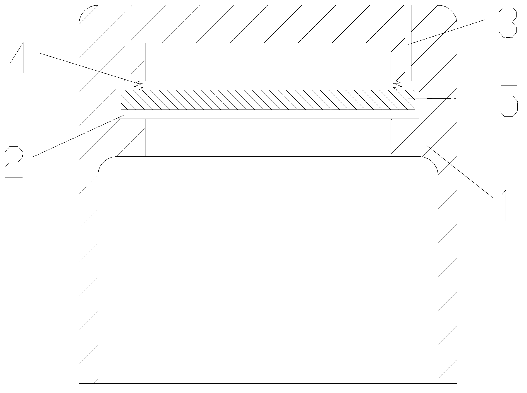
[0014] attached figure 1 , 2 It is a pressure relief device according to the present invention, which includes a disc-shaped housing 1, and the inner wall of the top of the housing 1 has an annular groove 2; the housing 1 is also provided with a The air release hole 3 communicated with the annular groove 2; the annular groove 2 is connected with a baffle plate 5 by a spring 4, and the diameter of the baffle plate 5 is between the inner diameter and the outer diameter of the annular groove 2, and the baffle plate 5 The thickness of the plate 5 is smaller than the width of the annular groove 2 .

[0015] The pressure relief device of the present invention is simple in structure and easy to use. During use, when the gas in the housing 1 acts on the baffle 5, the pressure formed is greater than the self-gravity of the baffle 5 and the elastic pressure of the spring 4 on it. At this time,...


PUM


Abstract

The invention discloses a pressure relief device which comprises a disk-shaped shell. The inner side wall of the top of the shell is provided with a ring-shaped groove; the shell is also provided with an air relief hole communicated with the ring-shaped groove; the inside of the ring-shaped groove is connected with a baffle by a spring; the diameter of the baffle is between the inner diameter and the outer diameter of the ring-shaped groove; and the thickness of the baffle is less than the width of the ring-shaped groove. The pressure relief device disclosed by the invention has a simple structure and is convenient to use; and as the gap between the ring-shaped groove in the shell and the baffle is regulated by the pressure applied to the baffle by the air pressure, the gravity of the baffle and the elastic pressure applied to the baffle by the spring according, not only the requirement on pressure relief can be effectively met, but also the effect of automatically regulating the pressure can be implemented and production development of enterprises is promoted.

Description

technical field [0001] The invention relates to a pressure relief device, in particular to a pressure relief device with simple structure and convenient use. Background technique [0002] The pressure relief devices currently used in the market have complex structures and high manufacturing costs. They are used in some equipment that does not have strict pressure relief requirements, which will cause redundant structures and redundant functions, which will increase equipment The cost of use is not conducive to the production and development of enterprises. Contents of the invention [0003] In view of the above-mentioned technical problems, the object of the present invention is to provide a pressure relief device with simple structure and easy use. [0004] The technical solution of the present invention is achieved in this way: a pressure relief device includes a disc-shaped casing, and the casing has an annular groove on the inner wall of its top; the casing is also pr...

Claims


Application Information

Patent Timeline
Patent Type & Authority Applications(China)
IPC IPC(8): F16K17/04
Inventor 于祥喜
Owner SUZHOU MAIDER MACHINERY
Why Eureka
Try Eureka