Eureka AIR delivers breakthrough ideas for toughest innovation challenges, trusted by R&D personnel around the world.

End covers of LED (Light Emitting Diode) tubular lamp and LED tubular lamp

An LED tube lamp and end cap technology, applied in the field of LED lighting, can solve the problems of inconsistent length, poor quality, and high rejection rate of LED lamps, and achieve the effects of safe and reliable work performance, simple and reasonable structure, and material saving.

Inactive Publication Date: 2013-09-18
辽宁三维传热技术有限公司
View PDF5 Cites 0 Cited by
  • Summary
  • Abstract
  • Description
  • Claims
  • Application Information

AI Technical Summary

Problems solved by technology

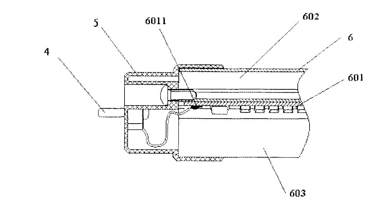
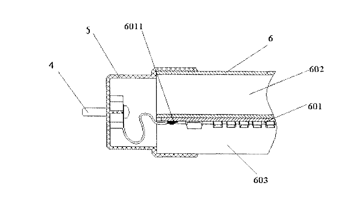
[0004] When assembling the LED lamp in the prior art, before connecting the lamp tube 6 and the end cover 5, it is necessary to connect the terminal 4 on the end cover with the conductive terminal 6011 of the lamp light source board 601 with a wire, and one end of the wire It is fastened to the end cover terminal 4 by screws, and the other end is welded to the conductive terminal 6011 of the light source board 601 of the lamp tube. These tasks are all done manually, which is cumbersome to install, low in efficiency, poor in quality, and high in maintenance rate.
During manual assembly, the amount of radiator and lampshade entering the end cap is not easy to control, which will lead to inconsistent lengths of the produced LED lamps, high scrap rate, and waste of materials
The welding process will produce harmful gases and pollute the environment
Manual assembly will also lead to weak connection between the lamp tube and the end cap, and poor sealing

Method used


Image

  • End covers of LED (Light Emitting Diode) tubular lamp and LED tubular lamp
  • End covers of LED (Light Emitting Diode) tubular lamp and LED tubular lamp
  • End covers of LED (Light Emitting Diode) tubular lamp and LED tubular lamp

Examples


Embodiment approach 1

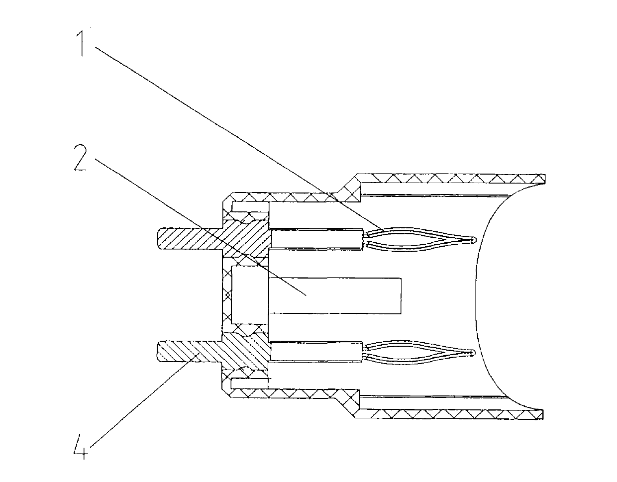
[0038] Figure 2A It is a sectional view of the end cover of the LED tube lamp of the present invention; Figure 2B It is the perspective view 1 of the end cap of the LED tube lamp of the present invention; Figure 2C It is the second perspective view of the end cap of the LED tube lamp of the present invention.

[0039] The end cap 5 for the LED tube lamp in this embodiment includes a terminal post 4, an elastic conductive cylinder 1, a buckle 2, and an end cap main body 501. The end cap 5 is in the shape of a straight rotary shell and is made of engineering plastics. Specifically, materials such as nylon, polycarbonate, and ABS can be selected. Two terminal posts 4 are fixedly installed on the bottom wall of the end cover 5 to provide a power supply circuit for the LED tube lamp. There is an annular boss 502 on the side wall of the end cover 5 close to the middle of its axial length. The open end is an arc structure, which facilitates the installation and cooperation of t...


PUM


Abstract

The invention discloses end covers of an (Light Emitting Diode) tubular lamp and the LED tubular lamp and belongs to the technical field of illuminating lamps. The LED tubular lamp comprises a lamp tube and two end covers, wherein the lamp tube consists of a heat radiator, a light source panel and a lamp shade; the two end covers are arranged at two ends of the lamp tube; a mounting groove is formed in the mounting surface of the heat radiator; the projection of a buckle is clamped in the mounting groove; partial heat radiating fins of the heat radiator are clamped in a clamping groove; an elastic conductive post body is inserted into a conductive terminal platform. The end covers of the tubular lamp and the LED tubular lamp provided by the invention have the advantages of simple and reasonable structure, capability of realizing automatic assembly, simpleness and convenience in mounting, high efficiency, safe and reliable work performance, low rejection rate, good sealing performance, material economization, environment friendliness and the like.

Description

technical field [0001] The invention relates to LED lighting technology, in particular to an end cover of an LED tube lamp and an LED tube lamp. Background technique [0002] With the rapid development of light emitting diode (Light emitting diode, LED for short) technology, LED lamps have been widely used at home and abroad. Existing LED lamps generally include a lamp tube and an end cover, wherein the lamp tube is generally assembled by a light source plate, a radiator and a semi-tubular lampshade; The incandescent lamp cap is basically the same, with a rotary shell-shaped end cover body, and includes a bottom wall, a side wall and an open end. There are wiring points inside the cover body. [0003] When assembling LED lamps in the prior art, the light source board is fixedly connected to the back of the radiator, the lampshade is covered on the light source board, and the two ends of the radiator and the lampshade are respectively fixedly installed in the shell of the e...

Claims


Application Information

Patent Timeline
IPC IPC(8): F21V21/002F21Y101/02
Inventor 张洪坤张俊杰
Owner 辽宁三维传热技术有限公司
Why Eureka
Eureka Blog
Learn More