Flexible joint angle sensor
A technology of angle sensors and flexible joints, which is applied in the direction of instruments and measuring devices, can solve problems such as limited application environment, complex system, and large detection error, and achieve the effects of high measurement accuracy, wide application fields, and simple and compact structure
- Summary
- Abstract
- Description
- Claims
- Application Information
AI Technical Summary
Problems solved by technology
Method used
Image
Examples
specific Embodiment approach 1
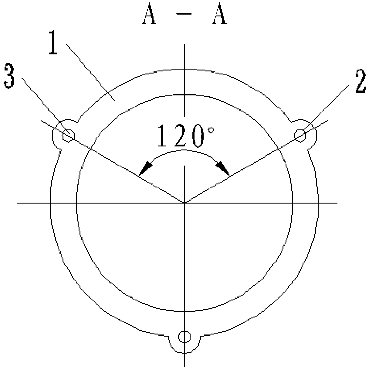
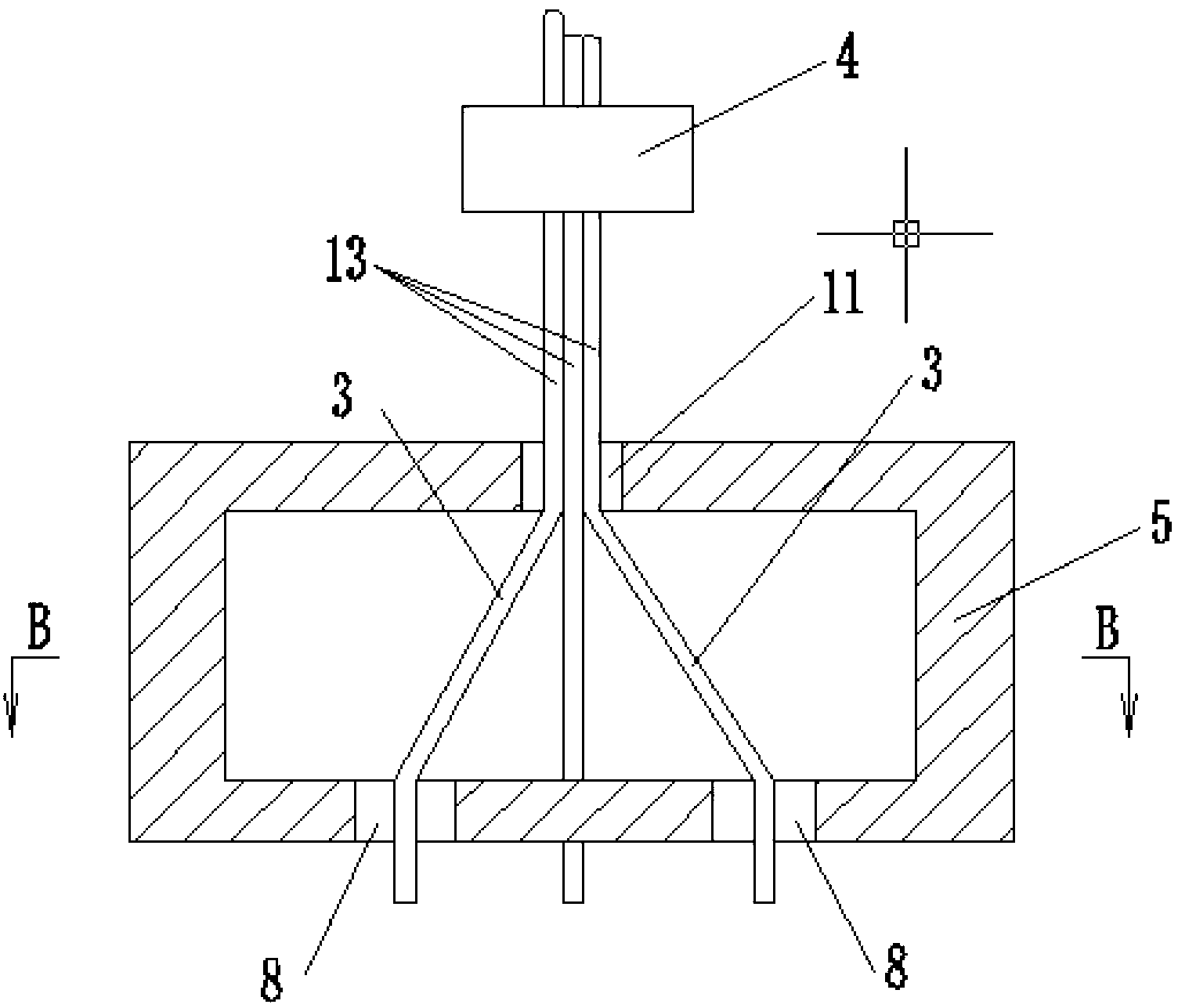
[0008] Specific implementation mode one: combine Figure 1 to Figure 6 Describe this embodiment. This embodiment includes a flexible bellows 1, an upper fixing block 4, a fixing ring 5, a lower fixing block 6, a displacement sensor 7, three steel wires 3 and several steel wire sliding tracks 2, and the flexible bellows 1 The upper end is connected with the fixed ring 5, and the lower end of the flexible bellows 1 is connected with the lower fixed block 6. Three steel wire sliding tracks 2 are evenly distributed along the circumference of each peak on the outer surface of the flexible bellows 1, and the surface of the flexible bellows 1 is along the The several steel wire slide rails 2 in the direction of the busbar are set facing up and down, the fixed ring 5 is a hollow structure, the center of the upper end surface of the fixed ring 5 is provided with a central hole 11, and the lower end surface of the fixed ring 5 is provided with three upper through holes 8 , the lower fix...
specific Embodiment approach 2
[0009] Specific implementation mode two: combination figure 2 To describe this embodiment, the three upper through holes 8 on the fixing ring 5 of this embodiment are uniformly distributed along the circumference. Design like this to make three steel wires 3 stressed evenly. Other components and connections are the same as those in the first embodiment.
specific Embodiment approach 3
[0010] Specific implementation mode three: combination image 3 , Figure 4 , Figure 5 , Figure 6 To describe this embodiment, the three lower through-holes 9 and the three upper through-holes 8 of this embodiment are arranged to face each other one by one. This design is convenient for the steel wires 3 to pass through, so that the three steel wires 3 are evenly stressed. Other components and connections are the same as those in the second embodiment.
PUM
 Abstract
Description
Claims
Application Information
 - R&D
- Intellectual Property
- Life Sciences
- Materials
- Tech Scout
- Unparalleled Data Quality
- Higher Quality Content
- 60% Fewer Hallucinations
Browse by: Latest US Patents, China's latest patents, Technical Efficacy Thesaurus, Application Domain, Technology Topic, Popular Technical Reports.
© 2025 PatSnap. All rights reserved.Legal|Privacy policy|Modern Slavery Act Transparency Statement|Sitemap|About US| Contact US: help@patsnap.com


