Method and system for determining infrared data sampling time

A technology of sampling time and infrared data, which is applied in the field of infrared positioning, can solve the problems of reducing the positioning accuracy and sensitivity of infrared touch screens, and the inability to judge touch events, etc., and achieve the effects of improving positioning accuracy and sensitivity, wide application range, and low cost

Inactive Publication Date: 2013-09-18
GUANGDONG VTRON TECH CO LTD
View PDF3 Cites 2 Cited by
  • Summary
  • Abstract
  • Description
  • Claims
  • Application Information

AI Technical Summary

Problems solved by technology

When the infrared receiving tube that has entered the supersaturated state is blocked, it is likely that a large part of the infrared light is blocked by the infrared receiving tube, but since the infrared receiving tube is still in a saturated state at this time, the collected data is still not blocked The data at that time is the same, so the microcomputer system cannot judge the touch event at this time according to the data collected by the infrared receiving tube, which will greatly reduce the positioning accuracy and sensitivity of the infrared touch screen

Method used


Image

  • Method and system for determining infrared data sampling time
  • Method and system for determining infrared data sampling time
  • Method and system for determining infrared data sampling time

Examples


Embodiment 1

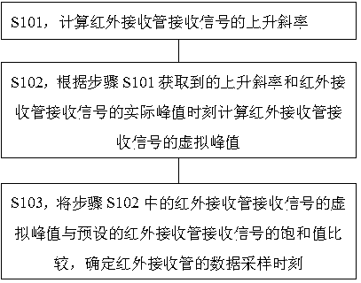
[0027] Such as figure 1 Shown is a flow chart of a specific embodiment of a method for determining an infrared data sampling time according to the present invention. see figure 1 , a kind of infrared data sampling moment determination method of the present specific embodiment comprises the following steps:

[0028] S101, calculate the rising slope of the received signal of the infrared receiving tube; wherein, when the infrared receiving tube receives the signal, a series of received signals will be obtained, and there is an upward trend or a downward trend between the received signal values, by calculating the received signal in the upward trend The slope formed between the values ​​is taken as the rising slope.

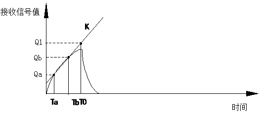
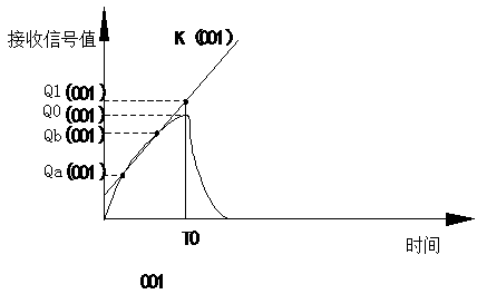
[0029] S102, calculate the virtual peak value of the signal received by the infrared receiving tube according to the rising slope obtained in step S101 and the actual peak time of the signal received by the infrared receiving tube; there is a peak sampling time in...

Embodiment 2

[0047] Such as Figure 5 As shown, it is a schematic diagram of the result of a specific embodiment of the infrared data sampling time determination system of the present invention. see Figure 5 , the infrared data sampling time determination system of this specific embodiment specifically includes:

[0048] The slope acquisition module 11 is used to calculate the rising slope of the curve corresponding to the upward trend of the infrared receiving tube receiving signal value; wherein, when the infrared receiving tube receives the signal, a series of receiving signals can be obtained, and there is an upward trend between the receiving signal values. For a downward trend, the slope acquisition module 11 calculates the slope formed between the received signal values ​​in an upward trend as the upward slope.

[0049] The peak calculation module 12 is used to calculate the virtual peak value of the signal received by the infrared receiving tube according to the obtained rising ...

Embodiment approach

[0055] As a preferred implementation, the data sampling moment determination module 13 includes:

[0056] The difference acquisition module is used to make a difference between the virtual peak value of the infrared receiving tube receiving signal and the preset saturation value of the infrared receiving tube receiving signal; wherein, the saturation value of the infrared receiving tube receiving signal is obtained by the difference acquiring module in advance Setting, it can be set as the maximum working voltage parameter of the infrared receiving tube, the maximum working voltage parameter can be queried from the specifications or instructions of the infrared receiving tube, or can be set according to the actual situation, such as in a preferred In the method, in the no-touch state, the received signal value of the infrared receiving tube read at the actual peak time is taken as the saturation value of the infrared receiving tube.

[0057] The result judging module is used t...


PUM


Abstract

The invention relates to the technical field of infrared positioning, in particular to a method and a system for determining the infrared data sampling time. The method comprises the following steps: calculating the ascending slope of an infra-red receiving pipe in receiving signals; calculating a virtual peak value of the infra-red receiving pipe in receiving signals according to the ascending slope and a practical peak value time of the infra-red receiving pipe in receiving signals; and comparing the virtual peak value of the infra-red receiving pipe in receiving signals with a pre-arranged saturation value of the infra-red receiving pipe in receiving signals, so as to determine the data sampling time of the infra-red receiving pipe. According to the invention, the situation that the data acquisition is performed at the supersaturation time of the infra-red receiving pipe in receiving signals can be effectively avoided, and also the situation that when the light emitted by the infra-red receiving pipe is shielded, the acquired receiving signals are still in a saturation value is avoided; and meanwhile, the receiving sensitivity of the infra-red receiving pipe not in a supersaturation state is ensured, and the positioning accuracy and the sensitivity of the infrared positioning device are improved.

Description

technical field [0001] The present invention relates to the technical field of infrared positioning, and more specifically, to a method and system for determining the sampling time of infrared data. Background technique [0002] Infrared touch screen has the advantages of simple structure, high stability, high resolution, easy installation, etc., and is not affected by current, voltage and static electricity. mainstream products in the market. Its basic structure is to install several pairs of infrared emitting tubes and infrared receiving tubes in a certain order on the periphery of a display surface. These infrared emitting tubes and infrared receiving tubes form a transmitting and receiving pair in a one-to-one correspondence, forming a mutually perpendicular transmitting and receiving array along the edge of the display surface, and the infrared rays emitted by each infrared emitting tube form a grid structure on the display surface Under the control of the microcomput...

Claims


Application Information

Patent Timeline
Patent Type & Authority Applications(China)
IPC IPC(8): G06F3/042
Inventor 李军明钟杰婷
Owner GUANGDONG VTRON TECH CO LTD
Why Eureka
Try Eureka