Magnetic modulation motor and electric transmission

A magnetic modulation and motor technology, applied in the direction of electric components, electromechanical transmission devices, magnetic circuit rotating parts, etc., can solve the problems of difficult to support magnetic modulation components, difficult to realize, etc.

Inactive Publication Date: 2013-09-18
DENSO CORP
View PDF1 Cites 8 Cited by
  • Summary
  • Abstract
  • Description
  • Claims
  • Application Information

AI Technical Summary

Problems solved by technology

On the other hand, as mentioned above, the magnetic modulation element is placed in the path of the magnetic flux going and returning between the armature and the field element, thereby causing the generation of eddy current
Such generation of eddy currents makes it difficult to support the magnetic modulation element by using metal members
[0032] Also, in the configuration disclosed in JP-B2-4505524, two inverters called PDUs (Power Drive Units) are required, so in the second case where the first rotary machine and the second rotary machine are arranged radially It is equally difficult to realize the two rotors described above in

Method used


Image

  • Magnetic modulation motor and electric transmission
  • Magnetic modulation motor and electric transmission
  • Magnetic modulation motor and electric transmission

Examples


Embodiment Construction

[0129] Hereinafter, exemplary embodiments according to the present invention will be described in detail with reference to the accompanying drawings.

[0130] (first exemplary embodiment)

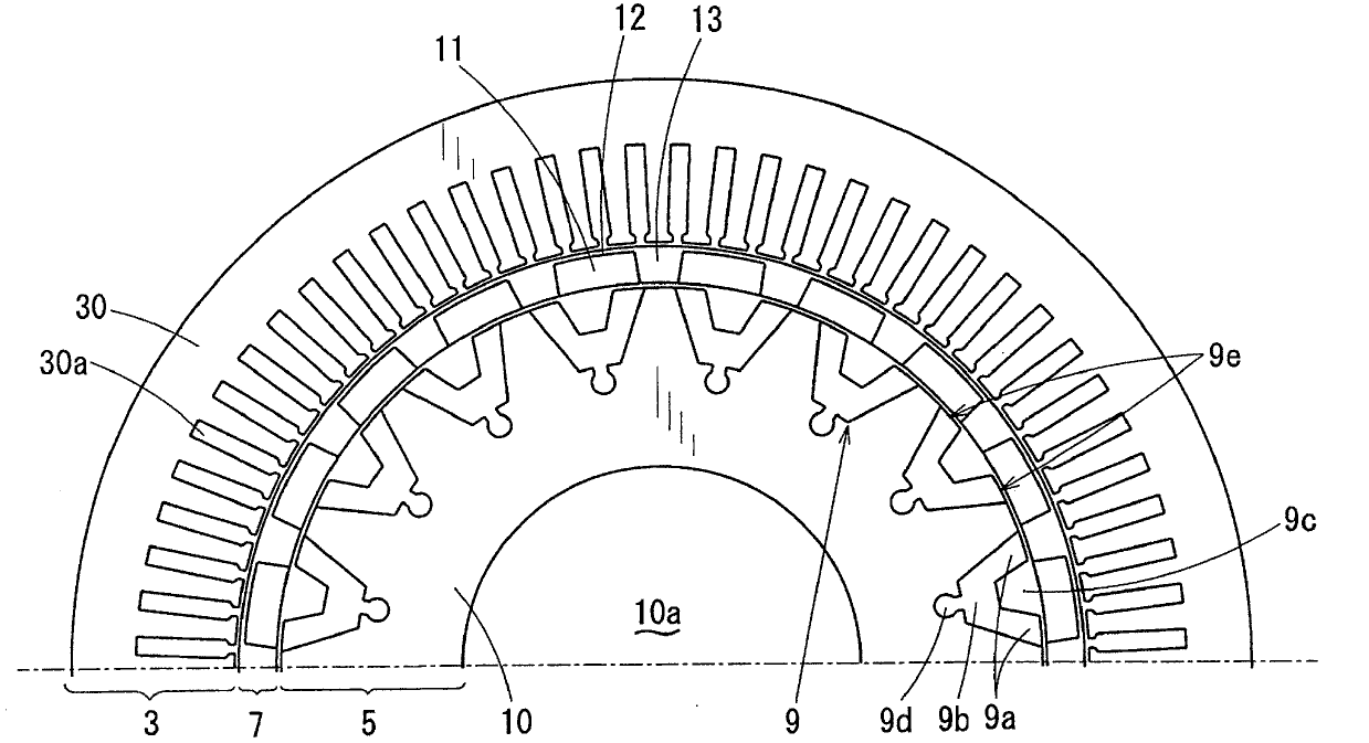
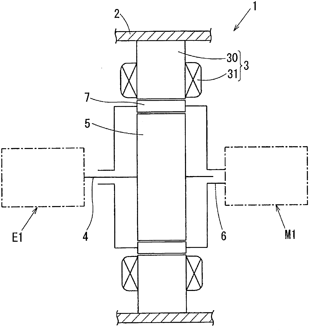
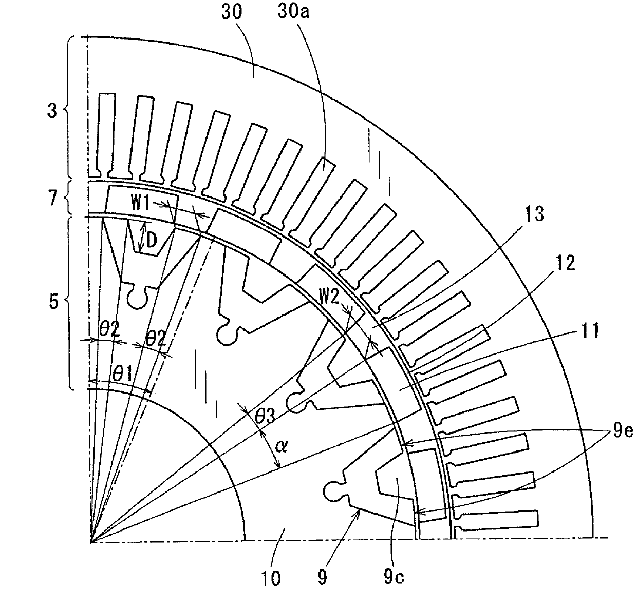
[0131] Figure 1 to Figure 4 A magnetic modulation motor (hereinafter referred to as "motor") 1 according to a first exemplary embodiment of the present invention is shown, which is installed between an engine and a transmission in a hybrid vehicle.

[0132] First, the configuration of the motor 1 will be described.

[0133] like figure 2 As shown in , the motor 1 includes a motor frame 2 , an armature 3 , a first rotating shaft 4 , a magnetic induction rotor 5 , a second rotating shaft 6 and a magnet rotor 7 . The armature 3 , the magnet rotor 7 , and the magnetic induction rotor 5 are arranged in this order from the radially outer side of the motor 1 to the radially inner side (center side) of the motor 1 . The armature 3 is fixed to the motor frame 2 . The first rotary shaft 4 is c...


PUM


Abstract

A magnetic modulation motor includes an armature, a magnetic induction rotor, and a magnet rotor. The armature is provided with a multi-phase winding with m pole pairs. The magnetic induction rotor includes k magnetic paths. In the magnet rotor, 2n permanent magnets forming a polarity region with n pole pairs are separately and annularly placed. The armature, the magnet rotor, and the magnetic induction rotor are arranged in the order from a radially outer side to a radially inner side. In the magnetic induction rotor, the magnetic path has two ends projecting toward a magnetic flux entry and exit located at an outer diameter face of the magnetic induction rotor, and forms a magnetic flux path between the magnetic flux entry and exit. The magnet rotor includes magnetic flux penetration region magnetically penetrated by magnetic flux between each circumferentially adjacent two permanent magnets.

Description

technical field [0001] The present invention relates to a magnetically modulated motor and electric transmission suitable for use in a powerplant for a hybrid vehicle driven by mechanical power from an internal combustion engine and electric power from a battery. Background technique [0002] As a related technology of a power transmission device for a hybrid vehicle, there is a common device that transmits power between an output shaft of an internal combustion engine and an input shaft of a gear through a motor and a CVT (Continuously Variable Transmission) Toggles between deceleration and back and forth motion. Recently, new techniques combining these functions have been proposed. [0003] For example, there is known a motor having a hybrid function that includes an armature corresponding to a stator, a magnet rotor fixed to a first rotation shaft, and a magnetic induction rotor fixed to a second rotation shaft. Based on the principle of magnetic modulation, the motor s...

Claims


Application Information

Patent Timeline
Patent Type & Authority Applications(China)
IPC IPC(8): H02K16/02H02K1/27
CPCH02K16/02H02K17/165H02K21/14H02K51/00
Inventor 草濑新要阳介樱井尚人
Owner DENSO CORP
Why Eureka
Try Eureka