
Weaving machine with lubricating systems

A technology for lubricating systems and looms, applied in engine lubrication, textiles, mechanical equipment, etc., can solve problems such as reduced lubricating performance and shortened service life of lubricating oil

Active Publication Date: 2013-09-18
PICANOL NV
View PDF11 Cites 2 Cited by
  • Summary
  • Abstract
  • Description
  • Claims
  • Application Information

AI Technical Summary

Problems solved by technology

At too high temperature of the lubricating oil, the service time of the lubricating oil is significantly shortened and the lubricating performance is significantly reduced

Method used


Image

  • Weaving machine with lubricating systems
  • Weaving machine with lubricating systems
  • Weaving machine with lubricating systems

Examples


Embodiment Construction

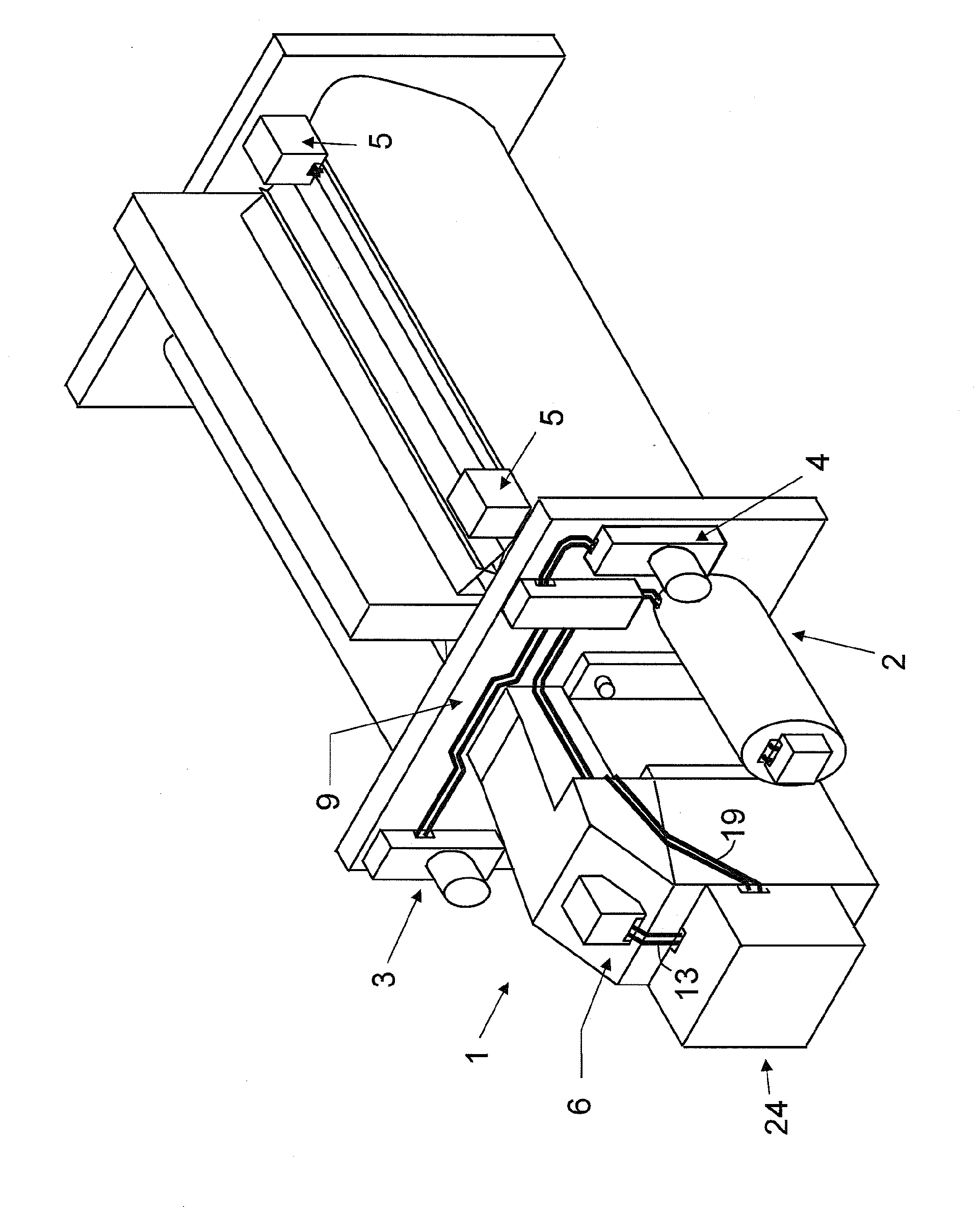
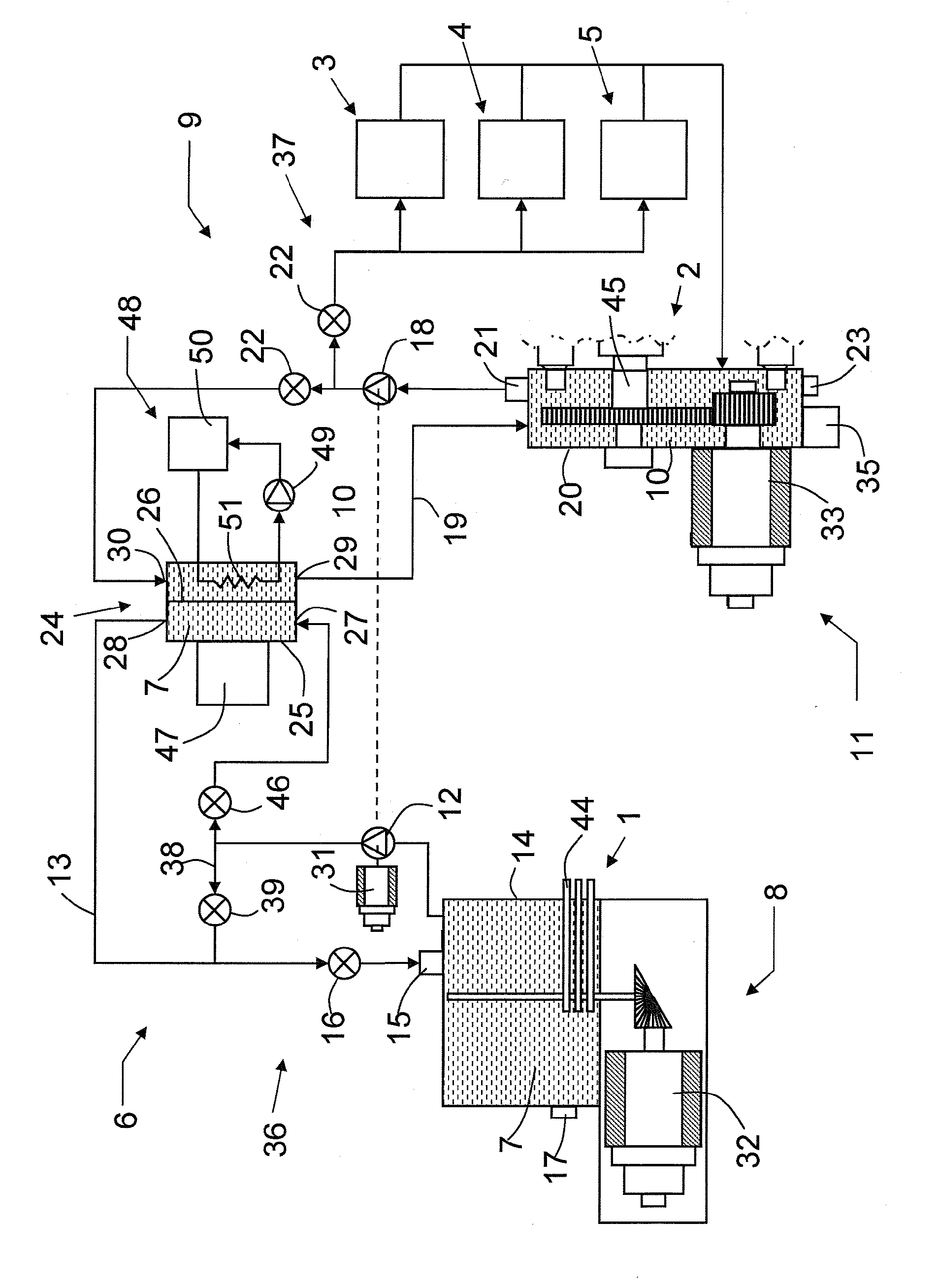
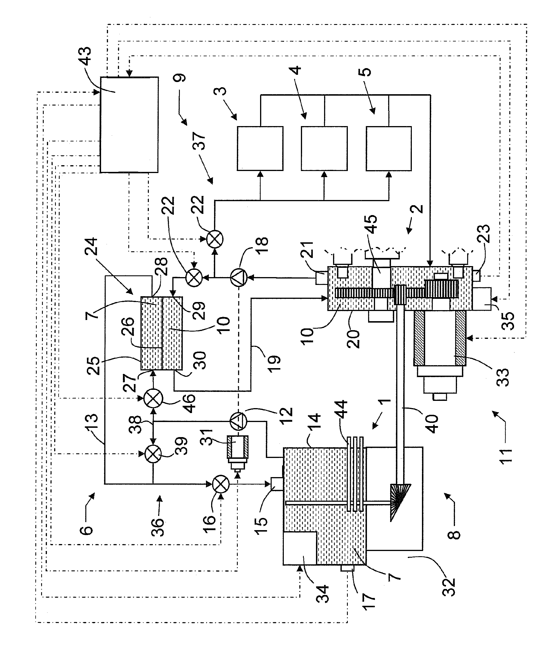
[0024] figure 1 and figure 2 A loom with a shed forming device 1 , a weft beating device 2 , a warp beam device 3 , a cloth beam device 4 and a selvedge tucking-in device 5 is schematically represented. The weaving machine comprises a first lubricating system 6 supplying a first lubricating fluid 7 to an element 44 of a first machine arrangement 8 comprising a shedding arrangement 1 . The loom also comprises a second lubricating system 9 which supplies a second lubricating fluid 10 to the elements of a second machine device 11 comprising a beating device 2 , a warp beam device 3 , a beam cloth device 4 and a selvage tucking device 5 45. The shedding device 1 can be a dobby, a cam box, an eccentric system and a jacquard device. As the lubricating fluid 7, 10, lubricating oil having an appropriate viscosity is used.

[0025] The first lubricating system 6 comprises a pump 12 for the lubricating fluid 7, a pipe 13 for leading the lubricating fluid 7 to and from the machine a...


PUM


Abstract

Weaving machine and method for lubricating a weaving machine, that comprises a first lubricating system (6) and a second lubricating system (9), wherein the first lubricating system (6) supplies a first lubricating fluid (7) to elements (44) of a first machine device (8) and the second lubricating system (9) supplies a second lubricating fluid (10) to elements (45) of a second machine device (11), and wherein heat is exchanged between the first lubricating fluid (7) and the second lubricating fluid (10).

Description

technical field [0001] The invention relates to a weaving machine comprising a first lubricating system, wherein the first lubricating system supplies a first lubricating fluid to elements of a first machine arrangement. The invention also relates to a method for lubricating such a loom. Background technique [0002] A known lubricating system for weaving machines comprises an oil pump and oil ducts for guiding lubricating oil along the elements to lubricate these elements. By guiding the lubricating oil along the element, the element is lubricated and heat exchange takes place between the element and the lubricating oil. [0003] In EP 1 613 799 B1 a lubricating system is described in which lubricating oil is guided by an oil pump to the elements of the shed forming device to be lubricated. In this case, the lubrication system is used to lubricate the drive of the heald frame and to lubricate the transmission formed by the rods, which is arranged between the drive and the...

Claims


Application Information

Patent Timeline
IPC IPC(8): D03J1/00F16N7/38
Inventor G.格拉迪恩D.萨姆帕斯K.勒尔斯特雷特
Owner PICANOL NV
Learn More