Method for laterally localising the wheels of a vehicle

A positioning method, a technology of lateral position, applied in the direction of vehicle parts, tire measurement, tire parts, etc., can solve problems such as excessive length

Active Publication Date: 2014-12-10
CONTINENTAL AUTOMOTIVE FRANCE
View PDF5 Cites 0 Cited by
  • Summary
  • Abstract
  • Description
  • Claims
  • Application Information

AI Technical Summary

Problems solved by technology

[0011] However, if the acceleration measurements and the calculation of the sign of the phase shift angle between the two accelerometers are done in a continuous fashion, or at high frequency (say every 2 ms), the power supply to the unit (and thus life of the battery that powers the accelerometer and microprocessor that are integrated into the unit and perform the calculations)
[0012] On the other hand, if a reasonably long time interval is set between two acceleration measurements, long enough not to unnecessarily load the battery, this time interval may prove sufficient at low rotational speeds or for For wheels with large rim radii, a minimum number of acceleration measurements are taken per wheel revolution, but for high rotational speeds or for small rim radii this time interval may turn out to be too long

Method used


Image

  • Method for laterally localising the wheels of a vehicle
  • Method for laterally localising the wheels of a vehicle
  • Method for laterally localising the wheels of a vehicle

Examples


Embodiment Construction

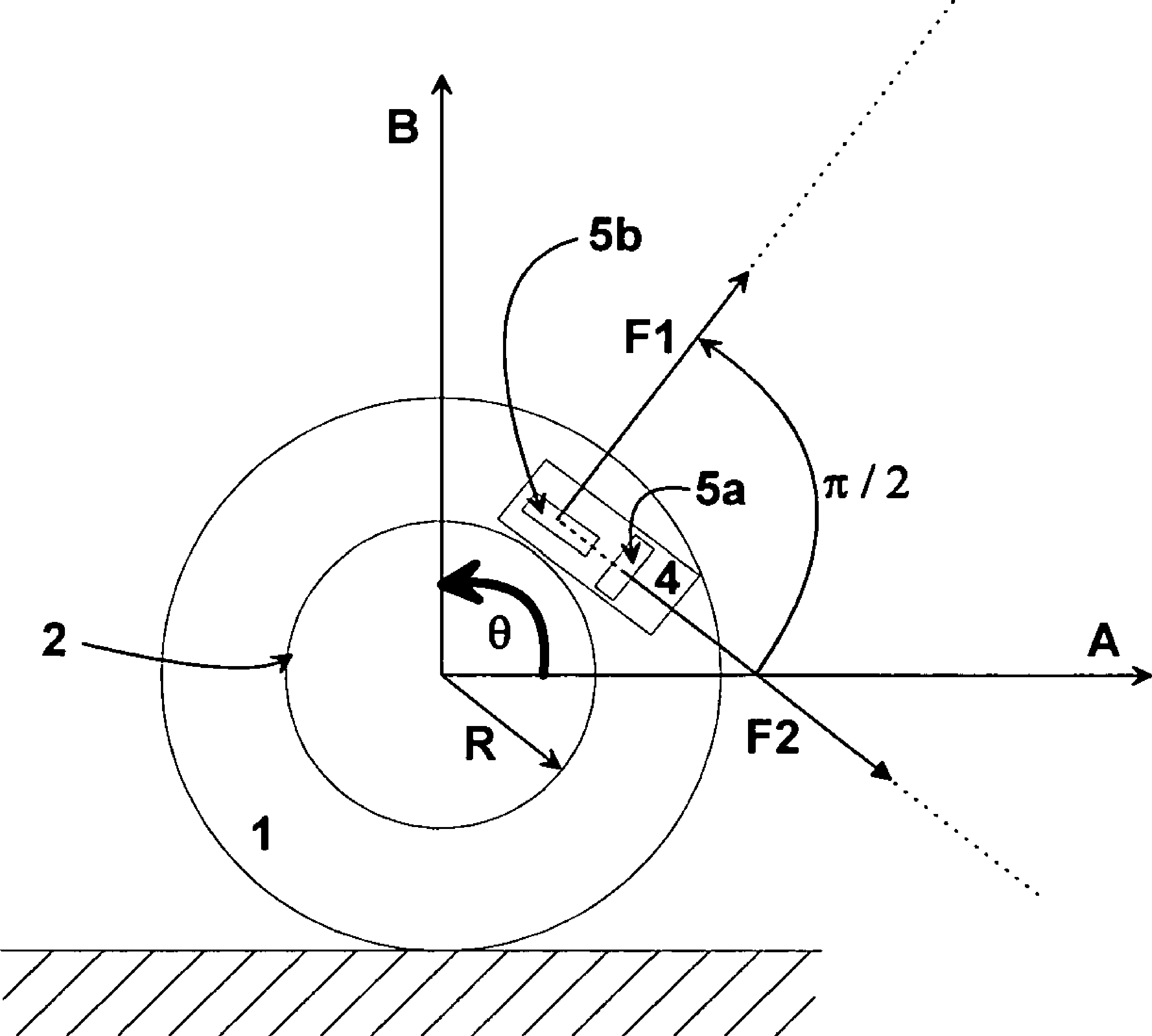
[0041] exist figure 1 A device for laterally positioning a vehicle wheel according to the invention is illustrated in . A vehicle (not shown) is equipped with a wheel 1 mounted on a rim 2 of radius R. The wheel 1 is equipped with a wheel unit 4 fixed to its rim 2 . Two accelerometers 5 a and 5 b are arranged within the wheel unit 4 . The two accelerometers 5a and 5b are perpendicular to each other such that the first accelerometer 5a is arranged tangentially with respect to the wheel and measures the tangential component of acceleration (this accelerometer will be called tangential accelerometer 5a), while the second accelerometer 5b is arranged radially with respect to the wheel and measures the radial component of acceleration (this accelerometer will be called radial accelerometer 5b). Therefore, by arrow F 1 and F 2 The offset value of their corresponding wheel acceleration measurement results represented by the phase shift angle.

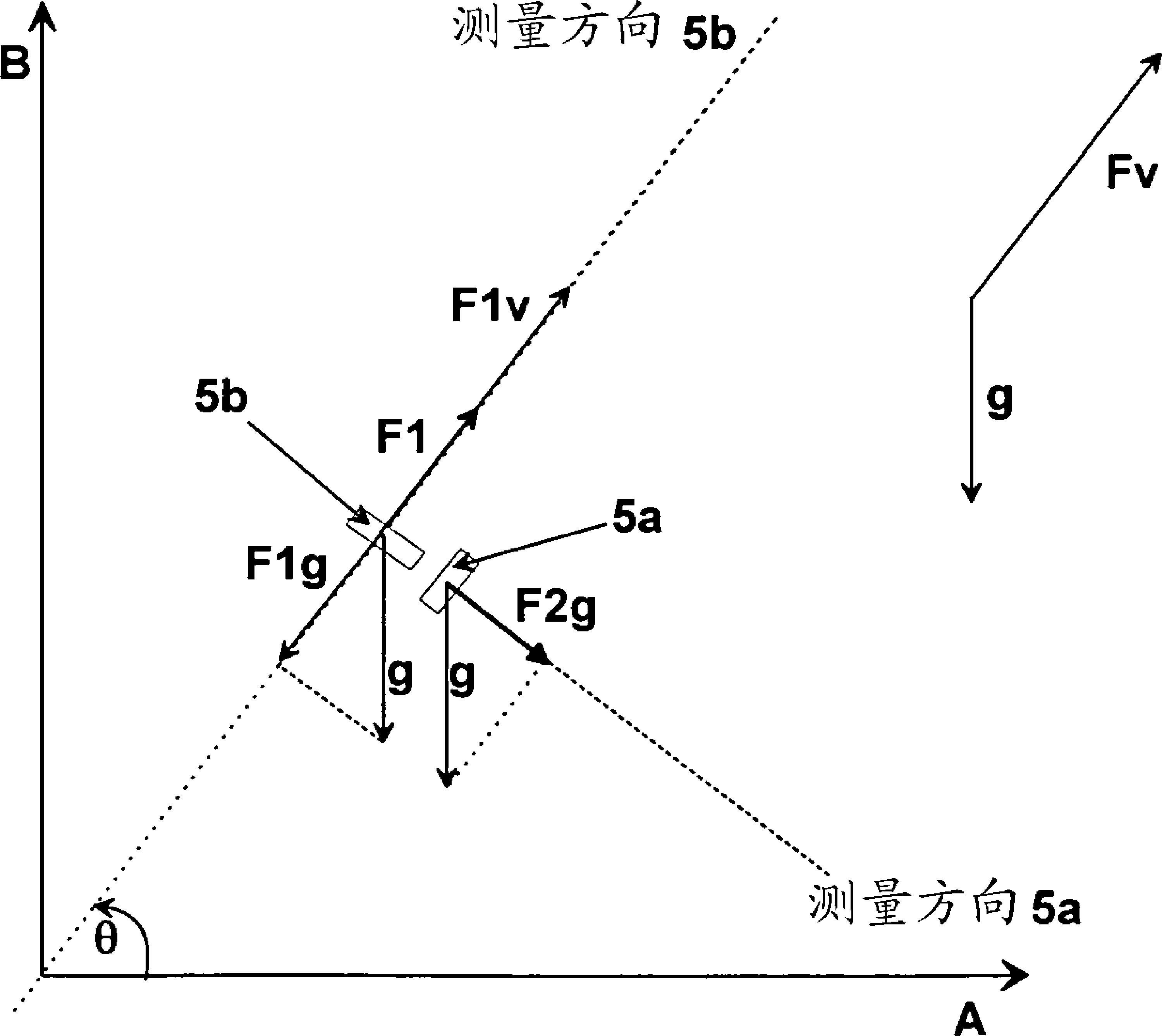
[0042] Such as figure 2 As show...


PUM


Abstract

Method for localization of the lateral position of the wheels of a vehicle equipped with a tire pressure monitoring system. Each wheel of the vehicle includes an electronic unit fixed onto a rim of radius R. Each unit notably includes two accelerometers, disposed perpendicular to one another and one measuring a radial component F1 of the acceleration, and the other a tangential component F2 of the acceleration. These components are out of phase by a predetermined phase-shift angle alpha. The method includes: I) measuring, per wheel rotation, at given intervals of time (Tmeasurement), a number (N) of acceleration values by each of the accelerometers (5a, 5b), II) calculating a physical value (P) representative of the sign of the phase-shift angle alpha between the two accelerometers, III) determining the lateral position of the wheel, based on the physical value (P) representative of the sign of the phase-shift angle.

Description

technical field [0001] The invention relates to a method for laterally positioning the wheels of a vehicle equipped with a tire pressure monitoring system. Background technique [0002] For safety reasons, automotive vehicles are increasingly equipped with tire pressure monitoring systems comprising sensors mounted on each wheel of the vehicle dedicated to measuring parameters such as the pressure and / or temperature of the tires equipped with these wheels and Designed to notify the driver of any abnormal changes in the measured parameters. [0003] These monitoring systems conventionally comprise, on the one hand, an electronic unit (also called a wheel unit) mounted on each wheel of the vehicle and incorporating, in addition to the aforementioned sensors, a microprocessor, an RF transmitter, and On the other hand, these monitoring systems comprise a central processing unit (mounted on the vehicle) for receiving the signals transmitted by the transmitter, said central proce...

Claims


Application Information

Patent Timeline
Patent Type & Authority Patents(China)
IPC IPC(8): G01D5/12B60C23/04
CPCB60C23/0416G01D5/12B60C23/0489
Inventor N.古恩尔特
Owner CONTINENTAL AUTOMOTIVE FRANCE
Why Eureka
Try Eureka