Capacitor electrode lead straightener

A straightening machine and lead wire technology, which is applied in the field of short metal cable straightening devices, can solve the problems of labor-intensive straightening effect, inconvenient installation and use of capacitors, and influence on product use, and achieve the effect of convenient operation

Active Publication Date: 2013-09-25
湖南华冉科技有限公司
16 Cites 1 Cited by

AI-Extracted Technical Summary

Problems solved by technology

Due to the thin lead wire of the capacitor pole, generally 0.3mm-0.8mm, it is easy to bend and deform during the insertion process, which affects the quality of the capacitor and brings inconvenience to the installation and use of the capacitor, so it needs to be straightened before leaving the factory. Lead handling...

Method used

[0028] The present invention cleverly utilizes the one-way movement characteristic of the ratchet mechanism, and the principle of leverage, and utilizes friction to drive the capacitor pol...

Abstract

The invention discloses a capacitor electrode lead straightener. The capacitor electrode lead straightener is characterized in that a support (3) is fixed on an operating table (2) through base bolts (4), a ratchet tooth cover (5-2) is fixed on the support (3) through ratchet bolts (12), a handle (7) is fixed on a ratchet pawl disc (5-1) which is used with the ratchet tooth cover (5-2), a rubber wheel (6) is fixed on the ratchet tooth cover (5-2) through a pin (1), an arc rubber plate (9) is fitted below the rubber wheel (6) and is fixed on a support plate (8), an adjustable lever support (11) is hinged to the middle of the support plate (8), an adjustable tension spring (10) is fixed at the other end of the support plate (8), and both the adjustable lever support (11) and the adjustable tension spring (10) are fixed on the operating table (2). The capacitor electrode lead straightener is fast and efficient, needs no extra energy source, and is energy-saving and environment-friendly.

Technology Topic

CapacitanceEngineering +4

Image

  • Capacitor electrode lead straightener
  • Capacitor electrode lead straightener
  • Capacitor electrode lead straightener

Examples

  • Experimental program(1)

Example Embodiment

[0023] In order to enable those skilled in the art to better understand the technical solutions of the present invention, the present invention will be described in detail below with reference to the accompanying drawings. The description in this section is only exemplary and explanatory and should not have any limitation on the scope of protection of the present invention. .
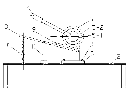
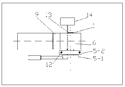
[0024] Such as Figure 1-2 As shown, the assembly relationship of the present invention is as follows: it includes an operating table 2 and a bracket 3. The bracket 3 is fixed on the operating table 2 by the base bolt 4, and the ratchet gear sleeve 5-2 is fixed on the bracket 3 by the ratchet bolt 12, and A handle 7 is fixed on the ratchet claw plate 5-1 matched with the ratchet gear sleeve 5-2; a rubber wheel 6 is fixed on the ratchet gear sleeve 5-2 by a pin 1; an arc rubber is fitted under the rubber wheel 6 The curved rubber plate 9 is fixed on the pallet 8, the middle of the pallet 8 is hinged with an adjustable lever bracket 11, the other end of the pallet 8 is fixed with an adjustable tension spring 10, the adjustable lever bracket 11 and The adjustable tension springs 10 are all fixed on the console 2.
[0025] During specific work, slightly pinch the capacitor 14 with your hand, and place the capacitor electrode lead 13 that needs to be straightened horizontally on the curved rubber plate 9; at this time, shake the handle 7 up and down, and the ratchet claw plate 5-1 drives the ratchet teeth The sleeve 5-2 performs one-way intermittent movement, and the rubber wheel 6 fixed on the ratchet gear sleeve 5-2 performs the same one-way intermittent movement with the ratchet gear sleeve 5-2.
[0026] At the same time, the lever composed of the adjustable tension spring 10, the adjustable lever bracket 11 and the support plate 8 presses the capacitor electrode lead 13 to be straightened between the curved rubber plate 9 and the rubber wheel 6. Due to the flexibility of the spring, As a result, the capacitor lead 13 is not compressed and fixed or deformed due to pressure.
[0027] When the rubber wheel 6 rotates in one direction, the capacitor lead 13 to be straightened is pressed between the rubber wheel 6 and the curved rubber plate 9. Due to the frictional force, the capacitor lead 13 is forced to roll forward to achieve The purpose of straightening.
[0028] The invention cleverly utilizes the unidirectional motion characteristics of the ratchet mechanism and the principle of leverage, and uses friction to drive the capacitor electrode lead 13 to roll, thereby achieving the purpose of straightening. In this process, no additional energy consumption is required, energy saving and environmental protection.
[0029] It should be noted that in this article, the terms "include", "include" or any other variants thereof are intended to cover non-exclusive inclusion, so that a process, method, article or device including a series of elements not only includes which elements, It also includes other elements not explicitly listed, or elements inherent to the process, method, article, or equipment.
[0030] Specific examples are used in this article to illustrate the principle and implementation of the present invention. The description of the above examples is only used to help understand the method and core idea of ​​the present invention. The above are only the preferred embodiments of the present invention. It should be pointed out that due to the limited expression of words, there are objectively infinite specific structures. For those of ordinary skill in the art, the principle of the present invention is not deviated from the premise Next, several improvements, modifications or changes can also be made, or the above technical features can be combined in an appropriate manner; these improvements, changes or combinations, or the concept and technical solution of the invention can be directly applied to other occasions without improvement , Should be regarded as the protection scope of the present invention.

PUM

no PUM

Description & Claims & Application Information

We can also present the details of the Description, Claims and Application information to help users get a comprehensive understanding of the technical details of the patent, such as background art, summary of invention, brief description of drawings, description of embodiments, and other original content. On the other hand, users can also determine the specific scope of protection of the technology through the list of claims; as well as understand the changes in the life cycle of the technology with the presentation of the patent timeline. Login to view more.

Similar technology patents

Graphene film and preparation method therefor

Owner:CHANGZHOU FUXI TECH CO LTD

Driving working load calculation method of automobile driver

InactiveCN101690666AImprove accuracy and timelinessEasy to operate
Owner:BEIJING UNIV OF TECH

Classification and recommendation of technical efficacy words

  • easy to operate

Lancet device

InactiveUS7303573B2inexpensively mass-producedeasy to operate
Owner:ABBOTT DIABETES CARE INC

Rapid and non-invasive optical detection of internal bleeding

InactiveUS20050065436A1easy to operaterapid and accurate result
Owner:HO WINSTON ZONH +2
Why Eureka
Try Eureka