Check patentability & draft patents in minutes with Patsnap Eureka AI!

Moving mechanism for core box trolley of core-making machine

A technology of moving mechanism and movement box, which is applied in the direction of core, molding machine, manufacturing tools, etc. It can solve the problems of short service life of rollers and guide rails, complex overall structure, and roller detachment from guide rails, etc., achieving high reliability and simple overall structure , the effect of uniform wear

Active Publication Date: 2013-09-25
SUZHOU MINGZHI TECH
View PDF7 Cites 1 Cited by
  • Summary
  • Abstract
  • Description
  • Claims
  • Application Information

AI Technical Summary

Problems solved by technology

[0004] This type of structure has relatively high requirements for rollers or V-shaped wheels. Because the rollers and guide rails are usually in line contact with this structure, the stress is large, and the life of the rollers and guide rails is short. In addition, the support force during mold clamping is satisfied by using plane contact. The required structure will cause the roller to break away from the guide rail. In order to achieve positioning, the overall structure is more complicated. In addition, because the load of the core box usually changes, the overall weight is one ton to eight tons, and the change of pressure also has a certain impact on the life of the roller and guide rail. degree of influence

Method used


Image

  • Moving mechanism for core box trolley of core-making machine
  • Moving mechanism for core box trolley of core-making machine
  • Moving mechanism for core box trolley of core-making machine

Examples


Embodiment 1

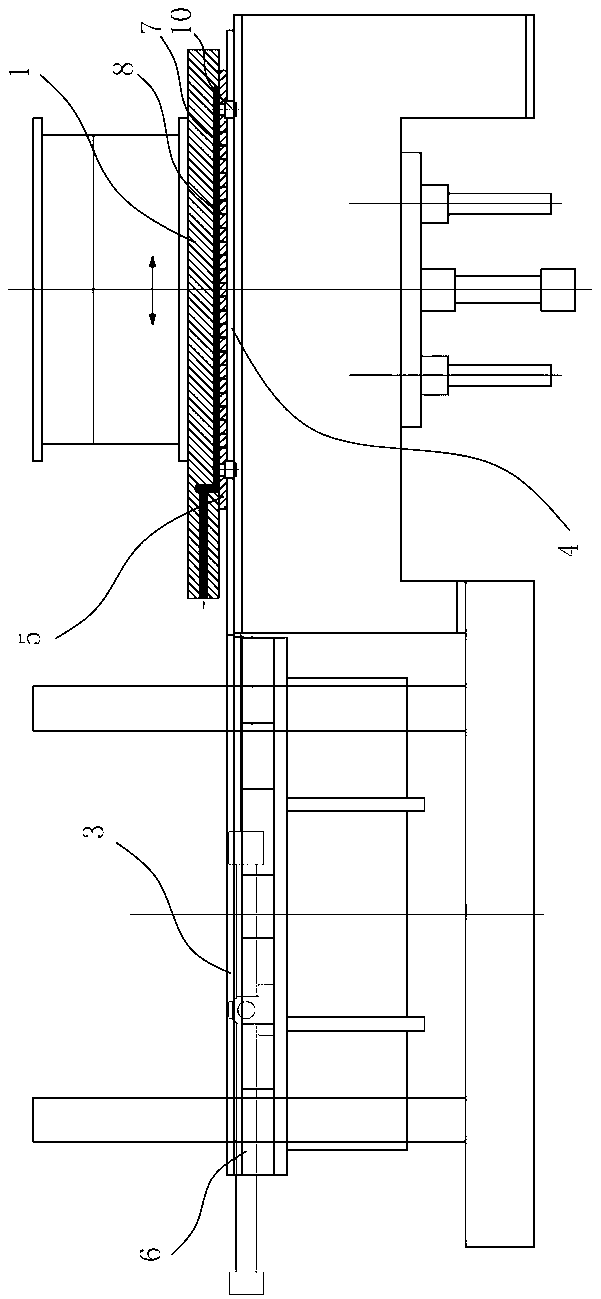
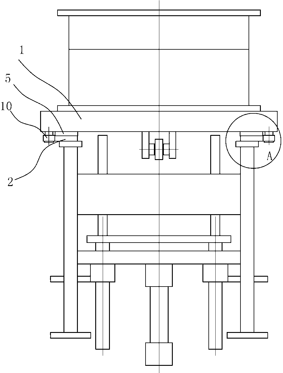
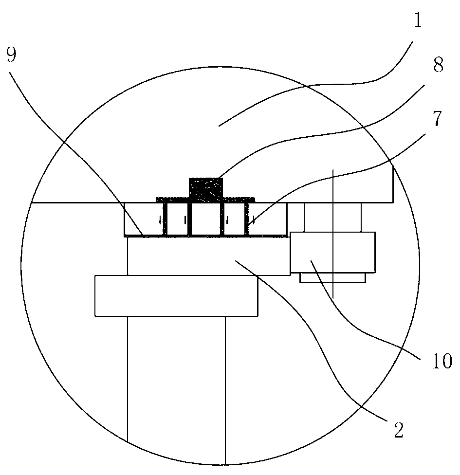
[0028] Embodiment one: see attached figure 1 to attach image 3 As shown, a core box trolley moving mechanism includes a core box trolley 1, a pair of guide rails 2 arranged in parallel, a driving structure and a guide structure, and the guide rails are composed of a workbench guide rail 3 and a lower top core guide rail 4. , the bottom of the core box trolley 1 is fixedly connected with a pair of support plates 5, a plurality of air holes 7 are distributed on the support plate 5, an air cavity 8 is provided at the bottom of the core box trolley, and the bottom of the air cavity 8 is connected to the support plate The air hole 7 on the top is connected, and one end of the air chamber 8 is connected to the compressed air source through the air pipeline. In the air pipeline, there is a lubricator, and the lubricator has a device for atomizing liquid oil and mixing it with compressed air. Structure; the lower surface of the support plate 5 is a plane, which is matched with the p...

Embodiment 2

[0031] Embodiment 2: A moving mechanism for a core box trolley, comprising a core box trolley 1, a pair of guide rails 2 arranged in parallel, a drive structure 3 and a guide structure 4, the guide rails are composed of a workbench guide rail 3 and a lower core guide rail 4 connection structure, the bottom of the core box trolley 1 is fixedly connected with a pair of support plates 5; the lower surface of the support plate 5 is a plane, which is matched with the workbench guide rail 3 or the lower top core guide rail 4 plane, and the workbench guide rail 3 or the upper surface of the lower top core guide rail 4 is distributed with a plurality of air holes 7, the guide rail is provided with an air cavity 8 communicating with the air holes, one end of the air cavity 8 is connected to a compressed air source through an air pipeline; the core box trolley 1 moves , there is an air cushion layer 9 between the lower surface of the support plate 5 and the guide rail 3 of the workbench ...


PUM

PropertyMeasurementUnit
Caliberaaaaaaaaaa

Abstract

The invention discloses a moving mechanism for a core box trolley of a core-making machine. The moving mechanism comprises a core box trolley, a pair of parallel guide rails, a driving structure and a guiding structure, wherein the guide rails are formed by connecting a workbench guide rail and a lower ejection core guide rail. The moving mechanism is characterized in that a pair of support plates are fixedly connected with the bottom of the core box trolley; a plurality of air holes are distributed in the support plates; an air cavity is formed in the bottom of the core box trolley; the bottom of the air cavity is communicated with the air holes formed in the support plates; one end of the air cavity is connected with a compressed air source by virtue of a gas pipeline; the lower surfaces of the support plates are planes and are matched with the plane of the workbench guide rail or the lower ejection core guide rail; when the core box trolley moves, an air cushion layer is arranged between the lower surfaces of the support plates and the workbench guide rail or the lower ejection core guide rail. According to the moving mechanism, the plane of the core box trolley is supported, by adjusting the pressure of compressed air, same sliding friction force of core boxes with different weights is realized, so that the guide rails are uniformly abraded, have an integrated structure and are long in service life and high in reliability.

Description

technical field [0001] The invention relates to a part of metal casting equipment, in particular to a moving mechanism of a core-making core box trolley. Background technique [0002] In the casting process, when preparing sand cores, the core box needs to move back and forth between the core making station and the lower core lifting station. At the core making station, the core box is lifted upwards to the lower surface of the sand shooting mechanism for Sand shooting operation, and then blowing air to solidify; at the lower core station, the cured sand core is ejected from the lower mold. The core box trolley is used to shuttle the core box back and forth between the core-making station and the lower core-jacking station, and is an important part of the core-making machine. [0003] In the existing core making machines, the structure of support rollers and side guide wheels is mainly used or V-shaped wheels are directly used to meet the back and forth movement and guidanc...

Claims


Application Information

Patent Timeline
IPC IPC(8): B22C15/24B22C9/10
Inventor 徐磊磊顾海兵
Owner SUZHOU MINGZHI TECH
Features
  • R&D
  • Intellectual Property
  • Life Sciences
  • Materials
  • Tech Scout
  • Unparalleled Data Quality
  • Higher Quality Content
  • 60% Fewer Hallucinations
Learn More