Assembly structure for tire pressure transmitter and inflating valve

A technology of tire pressure and assembly structure, applied in tire inflation valve, tire measurement, tire parts and other directions, can solve the problems of large change angle of antenna, large change angle of tire pressure transmitter, and degradation of signal transmission quality, and achieves the rotation point. Small force, small change angle, the effect of ensuring reliability

Active Publication Date: 2013-09-25
BAOLONG HUF SHANGHAI ELECTRONICS CO LTD
View PDF4 Cites 15 Cited by
  • Summary
  • Abstract
  • Description
  • Claims
  • Application Information

AI Technical Summary

Problems solved by technology

However, the change angle of the tire pressure transmitter is large, and the change angle of its antenna after assembly is also large, resulting in a decrease in signal transmission quality

Method used


Image

  • Assembly structure for tire pressure transmitter and inflating valve
  • Assembly structure for tire pressure transmitter and inflating valve
  • Assembly structure for tire pressure transmitter and inflating valve

Examples


Embodiment Construction

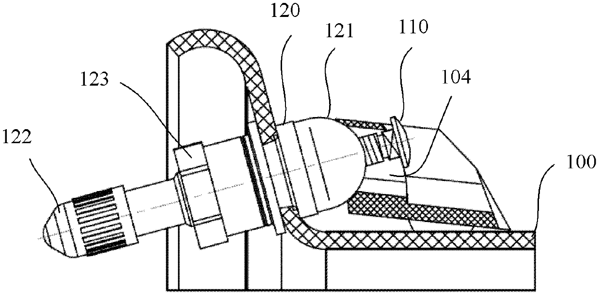
[0025] image 3 It is an exploded view of the assembly structure of the tire pressure transmitter and the valve according to the first embodiment of the present invention. Such as image 3 As shown, the assembly structure 200 includes a valve connector 201 , a small shaft 202 , a set screw 203 and a tire pressure transmitter connector 204 . The valve connecting head 201 is used for connecting the assembly structure 200 and the valve 210 . Here, the valve 210 is an ordinary valve. The tire pressure transmitter connector 204 is used to be combined with the casing 220 of the tire pressure transmitter so as to be connected with the assembly structure 200 .

[0026] In this embodiment, the valve connector 201 , the small shaft 202 , the set screw 203 and the tire pressure transmitter connector 204 are all independent components. The air valve connecting head 201 and the air valve 210 can be threaded.

[0027] combined reference Figure 7 As shown, the end face of the valve co...


PUM


Abstract

An assembly structure for a tire pressure transmitter and an inflating valve includes an inflating valve joint, a small shaft, a fastening screw and a tire pressure transmitter connecting member. The inflating valve joint has a lateral through hole diverging from the axis of the inflating valve joint in the downward direction. The tire pressure transmitter connecting member has an axial screw hole, one side of the screw hole is provided with a pivoting base, and the pivoting seat is provided with a pair of pivoting holes. The inflating valve joint is used for connecting an inflating valve; the tire pressure transmitter connecting member is used for combining with a housing of the tire pressure transmitter; the inflating valve joint is arranged on a pivoting part of the tire pressure transmitter connecting member; the small shaft passes through the pair of pivoting holes and the through hole of the inflating valve joint; the fastening screw is screwed into the screw hole of the tire pressure transmitter connecting member, when bearing against the end face of the inflating valve joint, the fastening screw goes on being screwed, so that the housing of the tire pressure transmitter rotates around the small shaft with the top end of the fastening screw as a fulcrum, until supporting points of the housing support to a tire rim.

Description

technical field [0001] The invention relates to a tire pressure transmitter installed on an automobile valve, in particular to an assembly structure of the tire pressure transmitter and the valve. Background technique [0002] The tire pressure monitor system (Tire Pressure Monitor System, TPMS) is a system that realizes real-time monitoring of tire pressure through a tire pressure sensing unit and a tire pressure monitoring unit using radio frequency communication. [0003] In order to realize real-time monitoring, the system installs a tire pressure transmitter on each tire, which can monitor the pressure and temperature in the tire and send it to the receiver in the car. In order to realize the fixed installation of the tire pressure transmitter and prevent it from falling off under various severe vehicle conditions, one installation method is to install the tire pressure transmitter on the rim of the tire and fix it with the valve. Because the tires of automobiles have ...

Claims


Application Information

Patent Timeline
Patent Type & Authority Applications(China)
IPC IPC(8): B60C23/04B60C29/06
CPCB60C23/0494
Inventor 王贤勇裘震芳
Owner BAOLONG HUF SHANGHAI ELECTRONICS CO LTD
Why Eureka
Try Eureka