Pipeline valve

A pipeline valve and valve body technology, which is applied in sliding valves, valve devices, engine components, etc., can solve the problems of increased production costs for enterprises and easy jamming of hard-sealed butterfly valves, so as to achieve great economic benefits, improve safety and reliability, and increase The effect of service life

Active Publication Date: 2013-09-25
JINCHUAN GROUP ENGINEERING AND CONSTRUCTION CO LTD
View PDF5 Cites 3 Cited by
  • Summary
  • Abstract
  • Description
  • Claims
  • Application Information

AI Technical Summary

Problems solved by technology

[0003] The purpose of the present invention is to provide a pipeline valve to solve the problem that the hard seal butterfly valve is easy to be blocked due to the transportation of flue gas with high dust content in the industrial production of sulfuric acid, and the frequent replacement of the valve increases the production cost of the enterprise

Method used


Image

  • Pipeline valve
  • Pipeline valve
  • Pipeline valve

Examples


Embodiment Construction

[0016] The technical scheme of the present invention will be described in further detail below in conjunction with the accompanying drawings.

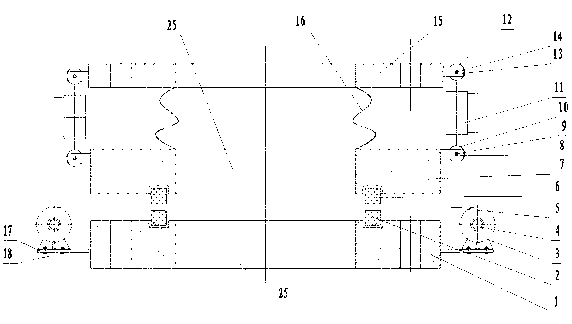
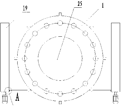
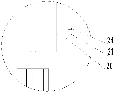
[0017] Such as Figures 1 to 4 A pipeline valve shown includes an upper valve body 7 and a lower valve body 1, the upper valve body 1 and the lower valve body 2 are oppositely provided with valve body holes 25 of the same size, and the two sides of the lower valve body 1 are symmetrical A reel 19 is provided, a belt-shaped valve core 5 is arranged between the upper valve body 7 and the lower valve body 1, and at least two valve core holes 23 are arranged on the belt-shaped valve core 5, and between two adjacent valve core holes 23 The distance is greater than the diameter of the valve body hole 25. One side of the strip valve core 5 is provided with three protrusions 24. Connected, the bottom surface of the upper valve body 7 is provided with an upper valve body seal 6, and the top surface of the lower valve body 1 is provided with a ...


PUM


Abstract

The invention discloses a pipeline valve which comprises an upper valve body and a lower valve body. Two valve body holes as large as each other are formed in the upper valve body and the lower valve body respectively. A strip valve element is disposed between the upper valve body and the lower valve body. A valve element hole is formed in the strip valve element. The valve element moves to allow overlap parts of the valve element hole and the valve body holes to change so as to achieve open and close of the valve element, simultaneously dust falling on the valve bodies and the valve element can be cleaned, and accordingly the problem of valve blockage caused by dust accumulation on the valve is solved effectively. A cylinder is disposed on the upper valve body, high-pressure air is fed into the cylinder to allow the upper valve body seal, the strip valve element and lower valve body seal to be compressed under pretightening force of the cylinder, and accordingly smoke leakage on the upper seal face and the lower seal face of the strip valve element is avoided, and production safety is increased. A telescopic joint is disposed on the upper valve body, so that the upper valve body can move flexibly. By the structure, the service life of the valve is prolonged greatly, production cost is saved, and huge economic benefits are brought to enterprises.

Description

technical field [0001] The invention relates to the technical field of valves, in particular to a pipeline valve, which is suitable for super-large pipeline valves used in transporting high-temperature gas with a lot of dust in industrial sulfuric acid production. Background technique [0002] The commonly used valves for transporting high-temperature flue gas pipelines in sulfuric acid production are hard-sealed flanged stainless steel butterfly valves, and the material is G / F 4 , The gap between the butterfly plate and the valve body of the hard-sealed butterfly valve is extremely small, and the butterfly valve for the flue is generally installed horizontally. The smelting flue gas contains a lot of dust and a large amount of saturated water. , easy to stick to the butterfly plate and the valve body, especially the lower valve body. After using for a period of time, the resistance of the valve switch gradually increases, and it is not easy to close, which affects the prod...

Claims


Application Information

Patent Timeline
Patent Type & Authority Applications(China)
IPC IPC(8): F16K3/314F16K3/02
Inventor 史万敬薛勇谢成张述荣程楚李山东高延润谭卫兵
Owner JINCHUAN GROUP ENGINEERING AND CONSTRUCTION CO LTD
Why Eureka
Try Eureka