Lubricating device for high-speed bearing in disc separator

A disc separator and high-speed bearing technology, which is applied in the direction of engine lubrication, centrifuges, bearing components, etc., can solve the problems of increasing the structural complexity of the machine base and the difficulty of processing.

Active Publication Date: 2013-09-25
ANHUI SAIERTE CENTRIFUGE
View PDF7 Cites 3 Cited by
  • Summary
  • Abstract
  • Description
  • Claims
  • Application Information

AI Technical Summary

Problems solved by technology

Oil pool lubrication requires a sealed machine base, so there are certain requirements for the sealing space of the high-speed rotating parts and the machine base, thus increasing the structural complexity and processing difficulty of the machine base

Method used


Image

  • Lubricating device for high-speed bearing in disc separator
  • Lubricating device for high-speed bearing in disc separator
  • Lubricating device for high-speed bearing in disc separator

Examples


Embodiment Construction

[0017] The present invention will be described in further detail below in conjunction with the accompanying drawings.

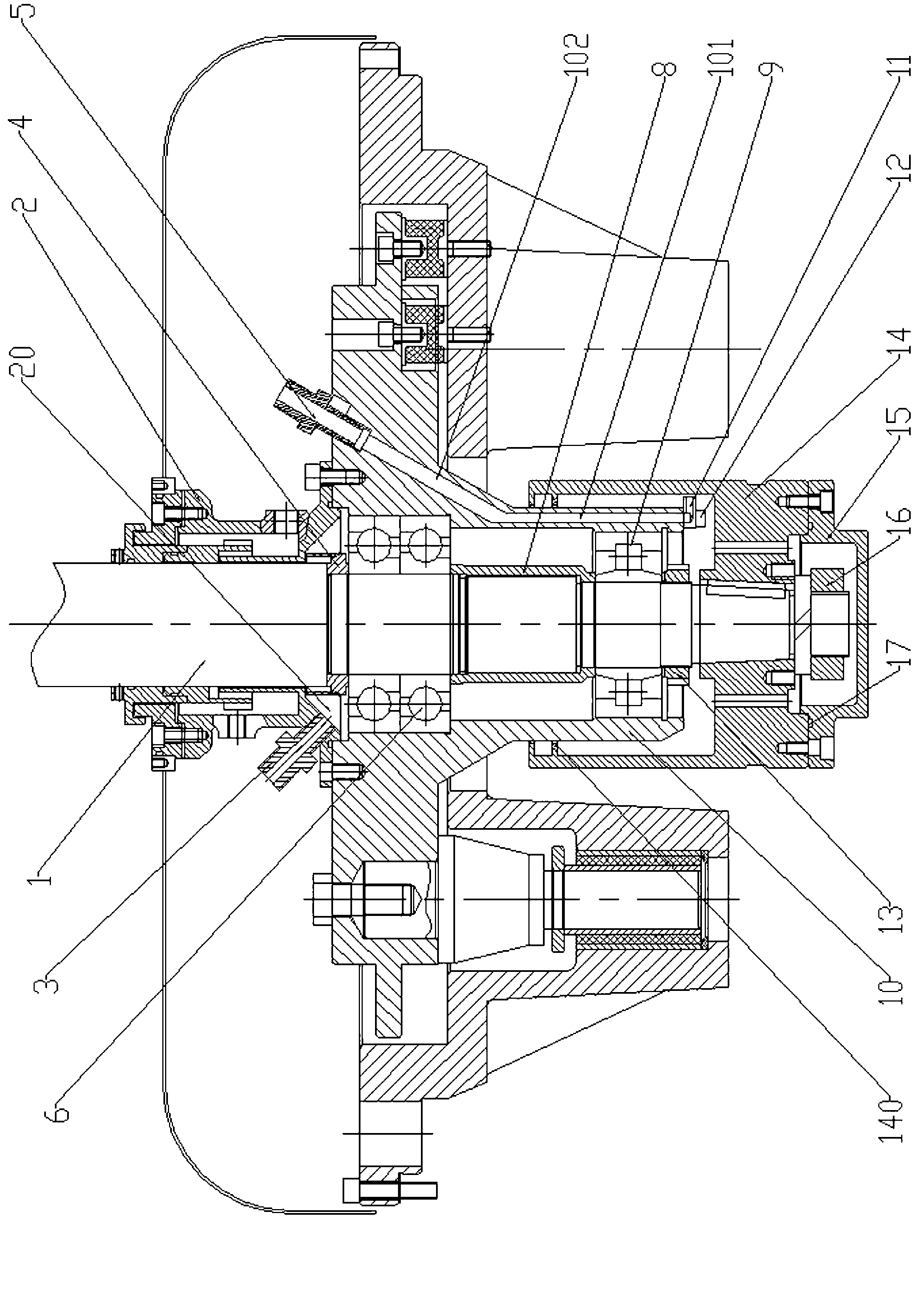
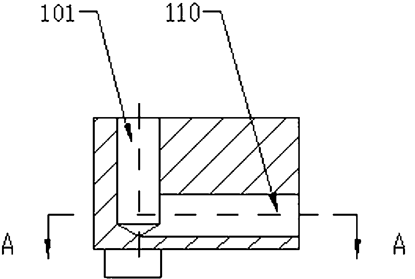
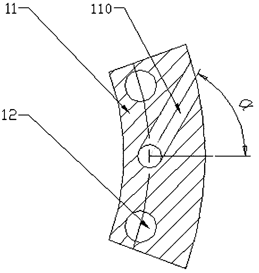
[0018] Depend on figure 1 , figure 2 and image 3 It can be seen that the high-speed bearing lubricating device of the disc separator of the present invention includes a vertical shaft 1 on which a coupling body 2 and a bearing seat 10 are set, and also includes an oil inlet joint 3 and an oil outlet joint 5. An oil throwing ring 4, at least one upper bearing 6, a spacer sleeve 8 and a lower bearing 9 are sequentially arranged on the vertical shaft 1 of the vertical shaft 1, the spacer sleeve 8 is installed between the upper bearing and the lower bearing, and there is a spacer between the spacer sleeve 8 and the inner wall of the bearing seat 10 gap. A lower lock cap 13 is arranged on the vertical shaft 1 at the lower end of the bearing block 10 to fix the lower bearing 9. There is a gap between the lower lock cap 13 and the inner cavity of the bearing se...


PUM


Abstract

The invention discloses a lubricating device for a high-speed bearing in a disc separator. The lubricating device comprises a vertical shaft, an oil inlet connector and an oil outlet connector. A coupling and a bearing block are sleeved on the vertical shaft. An oil slinger, at least one upper bearing, a spacer and a lower bearing are sequentially disposed on the vertical shaft inside the bearing block. A lower locking cap is disposed on the vertical shaft at the lower end of the bearing block. A belt pulley matching with the bearing block is connected to the tail end of the vertical shaft through a nut. The coupling is provided with a radial oil inlet. The upper end face of the bearing block is provided with a slant hole which deviates from the axis of the vertical shaft. The upper end of the slant hole is communicated with the oil outlet connector. An oil skimmer is connected to the lower end of the bearing block and is provided with a skimming hole. The skimming hole is communicated with the slant hole through a communicating hole in the bearing block. A gap is formed between the skimming hole and the inner wall of the belt pulley. The skimming hole radially deviates from the vertical shaft. The lubricating device has the advantages of good lubricating effect, long service life, simple structure, convenience in maintenance and low cost.

Description

technical field [0001] The invention relates to a disc separator, in particular to a lubricating device for a high-speed bearing of the disc separator. Background technique [0002] The disc separator is a kind of machine that performs separation work through high-speed rotation, and the bearing on the vertical shaft of the disc separator is the main working bearing on the disc separator. Lubrication has a great impact on the fatigue life of the bearing and friction, wear, vibration, etc. Important impact, without normal lubrication, the bearing will not work properly. About 40% of the causes of bearing damage are related to poor lubrication. Therefore, good lubrication of bearings is an effective measure to reduce friction and wear of bearings. At present, the bearing lubrication methods on the vertical shaft of the disc separator mainly include drip lubrication and oil pool lubrication. [0003] Drip oil lubrication uses a needle valve type oiling cup, which uses the w...

Claims


Application Information

Patent Timeline
Patent Type & Authority Applications(China)
IPC IPC(8): F16N7/14F16C35/12B04B15/00
Inventor 周海华
Owner ANHUI SAIERTE CENTRIFUGE
Why Eureka
Try Eureka