Lubricating device for bearing on vertical shaft of disc-type separator

A disc separator, bearing lubrication technology, applied in the direction of engine lubrication, centrifuges, mechanical equipment, etc., can solve the problems of inconvenient processing and maintenance, high mechanical cost, and achieve effective heat dissipation, low cost, and simple lubrication structure. Effect

Inactive Publication Date: 2010-06-30
ANHUI SAIERTE CENTRIFUGE
View PDF0 Cites 4 Cited by
  • Summary
  • Abstract
  • Description
  • Claims
  • Application Information

AI Technical Summary

Problems solved by technology

For oil pump lubrication, an oil pump needs to be installed in the frame, so

Method used


Image

  • Lubricating device for bearing on vertical shaft of disc-type separator
  • Lubricating device for bearing on vertical shaft of disc-type separator
  • Lubricating device for bearing on vertical shaft of disc-type separator

Examples


Example Embodiment

[0009] Below in conjunction with embodiment the present invention is described in further detail.

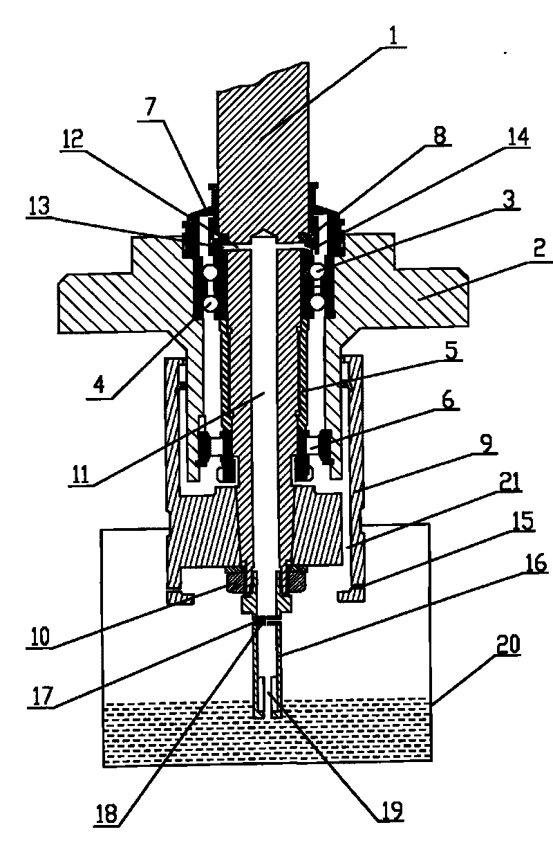
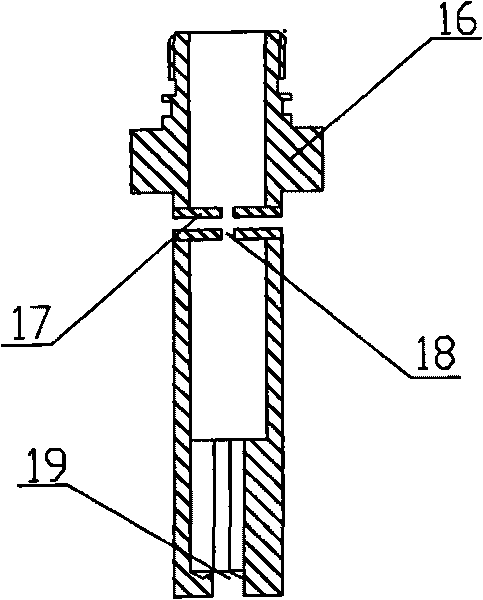
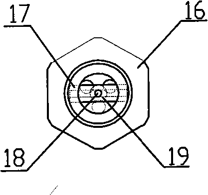
[0010] Depend on figure 1 , figure 2 and image 3 It can be seen that the bearing lubricating device on the vertical shaft of a disc separator according to the present invention includes a vertical shaft 1, a bearing seat 2, an upper bearing I3, an upper bearing II4, a spacer sleeve 5, a lower bearing 6, a gland 7, and a lubricating sleeve 8 , pulley 9, parallel nut 10; upper bearing I3, upper bearing II4, spacer sleeve 5, and lower bearing (6) are installed in the bearing seat 2 in sequence, and vertical shaft 1 passes through upper bearing I3, upper bearing II4, and spacer sleeve 5 in sequence , the lower bearing 6, a lubricating sleeve 8 is set on the vertical shaft 1 above the upper bearing 13, a gland 7 is also set on the vertical shaft 1 above the lubricating sleeve 8, and the belt pulley 9 is fixedly set on the vertical shaft 1 below the bearing seat 2, The central ax...


PUM


Abstract

The invention discloses a lubricating device for a bearing on the vertical shaft of a disc-type separator. The lubricating device comprises a vertical shaft, a bearing seat, an upper bearing I, and upper bearing II, a spacer sleeve, a lower bearing, a gland, a lubricating sleeve, a belt pulley and parallel tightening nuts. A blind hole is axially arranged in the center of the vertical shaft. A through hole is arranged at the bottom part of the blind hole. An annular oil groove is arranged on the lubricating sleeve. A small hole is arranged at the bottom of the annular oil groove and is communicated with the upper bearing I on the vertical shaft. A certain clearance is arranged between the spacer sleeve and the inner wall of the bearing seat. A through hole and a hole are respectively arranged on the end surface of the belt pulley and the bottom side surface of the belt pulley. The blind hole at the lower part of the vertical shaft is matched with the upper part of a suction tube. An axial through hole is arranged at the upper part of the suction tube. An air plug is transversely installed in a perforated hole at the middle part of the suction tube. An axial small hole is arranged at the lower part of the suction tube. Axial blind holes staggered with the small hole are arranged around the small hole, wherein the lower part of each axial blind hole is closed. The suction tube is arranged in an oil tank. The invention has the advantages that the accessories are reduced, the damage rate of the accessories is reduced and the lubrication effect is improved; and the structure is simple, the maintenance is convenient and the cost is low.

Description

(1) Technical field: [0001] The invention relates to a bearing lubricating device, in particular to a bearing lubricating device on a vertical shaft of a disc separator. (two) background technology: [0002] The disc separator is a kind of machine that performs separation work through high-speed rotation, and the bearing on the vertical shaft of the disc separator is the main working bearing on the disc separator. Lubrication has a great impact on the fatigue life of the bearing and friction, wear, vibration, etc. Important impact, without normal lubrication, the bearing will not work properly. About 40% of the causes of bearing damage are related to poor lubrication. Therefore, good lubrication of bearings is an effective measure to reduce friction and wear of bearings. At present, the bearing lubrication methods on the vertical shaft of the disc separator mainly include oil drop lubrication, oil pool lubrication, and oil pump lubrication. Drip oil lubrication uses a nee...

Claims


Application Information

Patent Timeline
IPC IPC(8): B04B15/00F16N7/14
Inventor 周海华陈啸吴义奇吴尚荣陈宗祥
Owner ANHUI SAIERTE CENTRIFUGE
Why Eureka
Try Eureka