A low-voltage power cabinet

A low-voltage power cabinet technology, applied in electrical components, substation/switch layout details, substation/distribution device shell, etc., can solve problems such as easy heating and poor cooling effect of low-voltage power cabinets, and achieve high heat dissipation efficiency. Good effect and easy to clean up

Active Publication Date: 2020-09-04
GUANGDONG POWER GRID CORP ZHAOQING POWER SUPPLY BUREAU
View PDF7 Cites 2 Cited by
  • Summary
  • Abstract
  • Description
  • Claims
  • Application Information

AI Technical Summary

Problems solved by technology

[0003] There are many electronic components in the commonly used low-voltage power cabinets, which are prone to heat during work. Therefore, low-voltage power cabinets often need to have better heat dissipation capabilities. The heat dissipation effect of low-voltage power cabinets in the prior art is poor.

Method used


Image

  • A low-voltage power cabinet
  • A low-voltage power cabinet
  • A low-voltage power cabinet

Examples


specific Embodiment approach 1

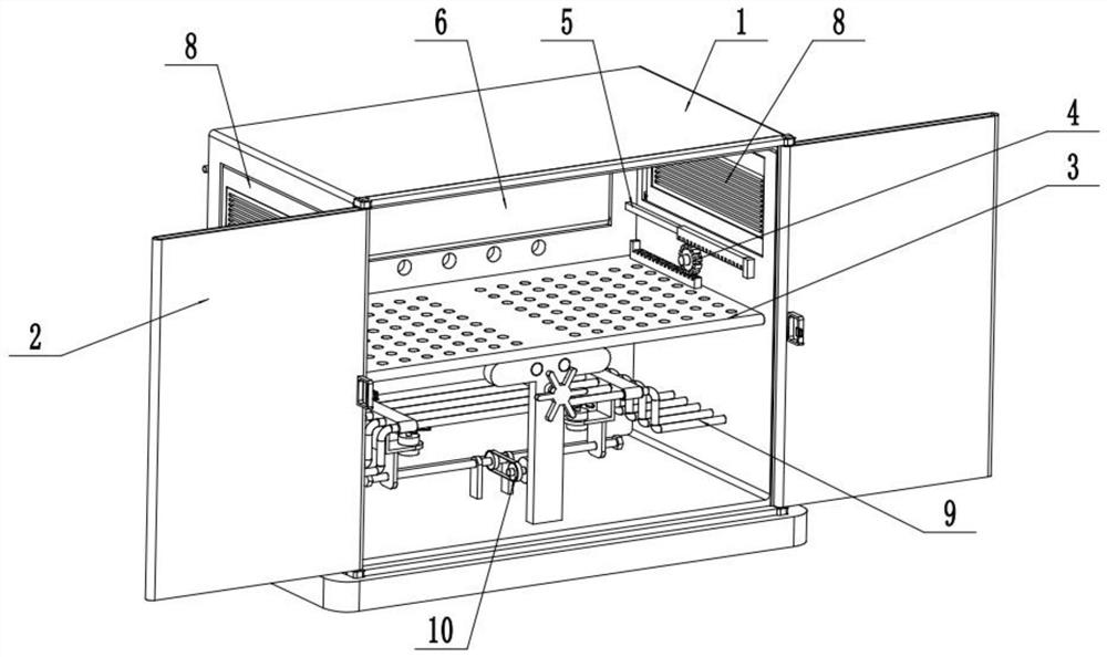
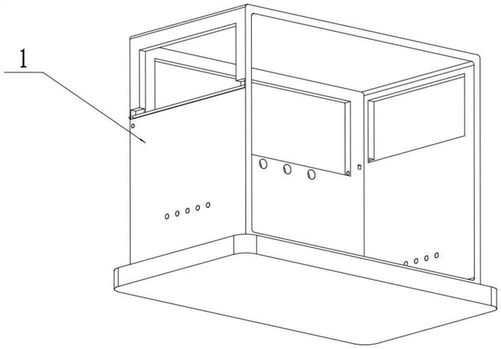
[0035] like Figure 1-15 As shown, a low-voltage power cabinet includes a cabinet body 1, a front cabinet door mechanism 2, a movable mounting plate mechanism 3, a direction changing wheel mechanism 4, a linkage opening and closing mechanism 5, a rear cabinet door mechanism 6, a transmission wheel mechanism 7, a side Cabinet door mechanism 8, water cooling mechanism 9 and air cooling mechanism 10, the front end of the cabinet body 1 is fixedly connected to the front cabinet door mechanism 2; the upper end of the movable mounting plate mechanism 3 is connected to the middle end inside the cabinet body 1, and is movably installed The lower end of the plate mechanism 3 is connected to the bottom surface inside the cabinet body 1; the left and right ends of the movable mounting plate mechanism 3 are respectively meshed and connected to a steering wheel mechanism 4, and the two steering wheel mechanisms 4 are respectively meshed and driven to connect a linkage. The opening and clos...

specific Embodiment approach 2

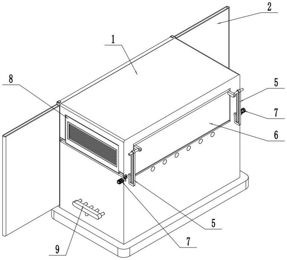
[0037] like Figure 1-15 As shown, the front cabinet door mechanism 2 includes an upper rectangular rod 2-1, a lower rectangular rod 2-2, a left rectangular rod 2-3, a right rectangular rod 2-4, a left sliding door 2-5, and a right sliding door 2 -6 and handle 2-7; the upper rectangular rod 2-1, the right rectangular rod 2-4, the lower rectangular rod 2-2 and the left rectangular rod 2-3 are sequentially fixed and connected to form a rectangular frame; the upper rectangular rod 2-1 and the rear ends of the lower rectangular rod 2-2 are respectively fixedly connected to the upper and lower ends of the front side of the cabinet body 1; the inner side of the left sliding door 2-5 is provided with a left rectangular sliding hole, and the left sliding door 2-5 The left rectangular sliding hole is slidably connected to the left rectangular rod 2-3; the inner side of the right sliding door 2-6 is provided with a right rectangular sliding hole, and the right sliding door 2-6 is slidab...

specific Embodiment approach 3

[0039] like Figure 1-15 As shown, the movable mounting plate mechanism 3 includes a mounting plate body 3-1 with a plurality of bolt connection holes on the top surface, a driving rack 3-2, a rear limit baffle 3-3, and a horizontal movable seat 3-4 , guide shaft 3-5, adjusting screw 3-6, screw disc 3-7, T-shaped vertical plate 3-8, hexagonal column 3-9 and tension spring 3-10; the top surface of the mounting plate body 3-1 The left and right ends of the driving rack 3-2 are respectively fixedly connected to a driving rack 3-2, the rear end of the top surface of the driving rack 3-2 is fixedly connected to the rear limit baffle 3-3, and the two driving racks 3-2 are meshed and connected to one The direction changing wheel mechanism 4; the horizontal movable seat 3-4 is fixedly connected to the rear end of the bottom surface of the mounting plate body 3-1; the front and rear ends of the guide shaft 3-5 are respectively fixedly connected to the T-shaped vertical plate 3-8 and t...


PUM


Abstract

The invention relates to the technical field of electric power, in particular to a low-voltage electric cabinet. The low-voltage electric cabinet comprises a cabinet body, a front cabinet door mechanism, a movable installation plate mechanism, steering wheel mechanisms, linkage opening and closing mechanisms, a rear cabinet door mechanism, a transmission wheel mechanism, a side cabinet door mechanism, a water cooling mechanism and an air cooling mechanism. The front end of the cabinet body is fixedly connected with the front cabinet door mechanism. The upper end of the movable installation plate mechanism is connected to the middle end inside the cabinet body, and the lower end of the movable installation plate mechanism is connected to the bottom surface inside the cabinet body. Each of the left and right ends of the movable installation plate mechanism is in meshed transmission connection with one steering wheel mechanism. Each of the two steering wheel mechanisms is in meshed transmission connection with one linkage opening and closing mechanism. The middle ends of the two linkage opening and closing mechanisms are respectively connected to the left and right ends of the rear end face of the cabinet body through sliding fit. The low-voltage electric cabinet is internally equipped with the water cooling mechanism and the air cooling mechanism, so that the heat of the electronic components inside the low-voltage power cabinet can be radiated, and a better heat dissipation effect and higher heat dissipation efficiency are achieved.

Description

technical field [0001] The invention relates to the field of electric power technology, in particular to a low-voltage power cabinet. Background technique [0002] Low-voltage power cabinets are the assembly of switchgear, measuring instruments, protective appliances and auxiliary equipment in a closed or semi-closed metal cabinet according to electrical wiring requirements. During normal operation, the circuit can be connected or disconnected with the help of manual or automatic switches. The measuring instrument can display various parameters during operation, and can also adjust some electrical parameters to prompt or send signals for deviations from the normal working state. [0003] There are many electronic components in the commonly used low-voltage power cabinets, which are easy to generate heat during operation. Therefore, the low-voltage power cabinets often need to have better heat dissipation capacity, and the low-voltage power cabinets in the prior art have poor...

Claims


Application Information

Patent Timeline
Patent Type & Authority Patents(China)
IPC IPC(8): H02B1/30H02B1/36H02B1/56H02B1/38
CPCH02B1/30H02B1/36H02B1/38H02B1/565
Inventor 李松杰
Owner GUANGDONG POWER GRID CORP ZHAOQING POWER SUPPLY BUREAU
Why Eureka
Try Eureka