LED luminous lamp pole

A technology of light-emitting lamps and light poles, which is applied in the direction of light source, light source fixation, point light source, etc. question

Inactive Publication Date: 2013-09-25
吕爱群
View PDF0 Cites 0 Cited by
  • Summary
  • Abstract
  • Description
  • Claims
  • Application Information

AI Technical Summary

Problems solved by technology

[0002] The current light-emitting light poles have a lot of practical application problems: the convex groove on the light-transmitting plate cannot be used effectively and conveniently, and the light-transmitting plate cannot be disassembled at will when it is installed in the groove corresponding to the profile, but must be removed from the light pole. Pulling out and inserting both ends, the recessed card slot will be covered with plastic powder when spraying, and its thickness will increase unevenly, so that the light-transmitting board that could have been inserted cannot be smoothly inserted into the groove of the profile
Once the product is formed, the light-transmitting board can only be inserted and installed from both ends of the profile, which adds to the difficulty
Because it is a tablet design, it cannot have a better light distribution effect

Method used


Image

  • LED luminous lamp pole
  • LED luminous lamp pole
  • LED luminous lamp pole

Examples


Embodiment 1

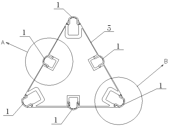
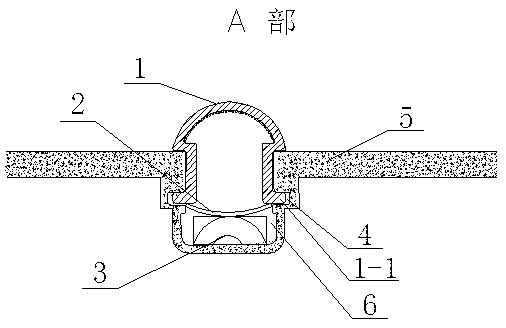
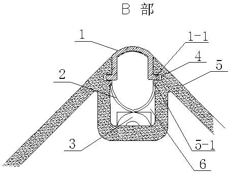
[0023] Such as figure 1 , 2 As shown in . Card slots 4 are provided on both sides of the light pole body 5 in each installation groove 6, and LED flexible light strips 3, transparent cards 2 and U-shaped light-transmitting plates 1 are respectively arranged in each installation groove 6. The light strips 3 are pasted on the light pole body 5 respectively, and the two sides of the opening end of each U-shaped light-transmitting plate 1 are separately provided with connecting flanges 1-1, and each connecting flange 1-1 is respectively arranged on the corresponding In the card slot 4, the arc sections of the three U-shaped light-transmitting plates 1 are respectively arranged outside the light pole body 5, and the three transparent cards 2 are respectively arranged on each U-shaped light-transmitting plate 1 and the corresponding LED soft light. between band 3. The two sides of the light pole body 5 in the other three mounting grooves 6 are respectively provided with bosses 5-...

Embodiment 2

[0025] Such as Figure 5 As shown, it is the second type of LED light-emitting light pole, which includes a circular light pole body 5 made of aluminum profiles, and the rest of the structure is the same as that of Embodiment 1.

[0026]

Embodiment 3

[0028] Such as Figure 6 As shown, it is the second type of LED light-emitting light pole, which includes a polygonal light pole body 5 made of aluminum profiles, and the rest of the structure is the same as that of Embodiment 1.


PUM


Abstract

An LED (Light Emitting Diode)luminous lamp pole relates to the field of illuminating lamps, and comprises a Lamp pole main body, wherein at least one mounting groove is formed outside the Lamp pole main body in the height direction of the lamp pole main body; clamping grooves are respectively formed in two sides of the Lamp pole main body in each mounting groove; an LED soft lamp belt, a transparent card and a U-shaped translucent plate are respectively arranged in each mounting groove; each LED soft lamp belt is pasted on the Lamp pole main body; edge connecting bulges are respectively arranged on two sides of the open end of each U-shaped translucent plate in a combined manner; each edge connecting bulge is respectively arranged in the corresponding clamping groove; each transparent card is respectively arranged between each U-shaped translucent plate and the corresponding LED soft lamp belt. The LED luminous lamp pole has the benefits that the problem that the translucent plates can not be mounted at will is solved, the height and the width of a light-emitting area can be adjusted according to different shapes of the translucent plates, and distribution of light of the LED lamp belts on the translucent plates can be changed correspondingly and more effectively.

Description

technical field [0001] The invention relates to the field of lighting fixtures, in particular to a light-emitting light pole used for street lights, garden lights, landscape lights, lawn lights, and light-emitting light poles for light sculpture sketches made of the elements. Background technique [0002] The current light-emitting light poles have a lot of practical application problems: the convex groove on the light-transmitting plate cannot be used effectively and conveniently, and the light-transmitting plate cannot be disassembled at will when it is installed in the groove corresponding to the profile, but must be removed from the light pole. Pulling out and inserting both ends, the recessed card slot will be covered with plastic powder when spraying, and its thickness will increase unevenly, so that the light-transmitting board that could have been inserted cannot be smoothly inserted into the groove of the profile . Once the product is formed, the light-transmitting...

Claims


Application Information

Patent Timeline
IPC IPC(8): F21V19/00F21Y101/02
Inventor 吕爱群
Owner 吕爱群
Why Eureka
Try Eureka