Shock test device

A technology of impact test and impact parts, which is applied in the field of impact test equipment, can solve the problems of low accuracy of impact test and inability to guarantee the impact of impact hammer, etc.

Inactive Publication Date: 2013-09-25
OCEANKING DONGGUAN LIGHTING TECH +2
View PDF6 Cites 7 Cited by
  • Summary
  • Abstract
  • Description
  • Claims
  • Application Information

AI Technical Summary

Problems solved by technology

When a 1kg impact hammer hits the test sample from a height h of free fall, since there is no corresponding control device for controlling the impact hammer, and human uncertain factors will cause the impact hammer to deviate, it is impossible to ensure that the impact hammer hits the point where it needs to be impacted position, thereby affecting the accuracy of the impact test, so the accuracy of this manually controlled impact test is low

Method used


Image

  • Shock test device
  • Shock test device
  • Shock test device

Examples


Embodiment Construction

[0029] In order to solve the problem of low accuracy of the impact test, an impact test device with high accuracy is proposed. The above-mentioned impact test device will be further elaborated below through specific embodiments and accompanying drawings.

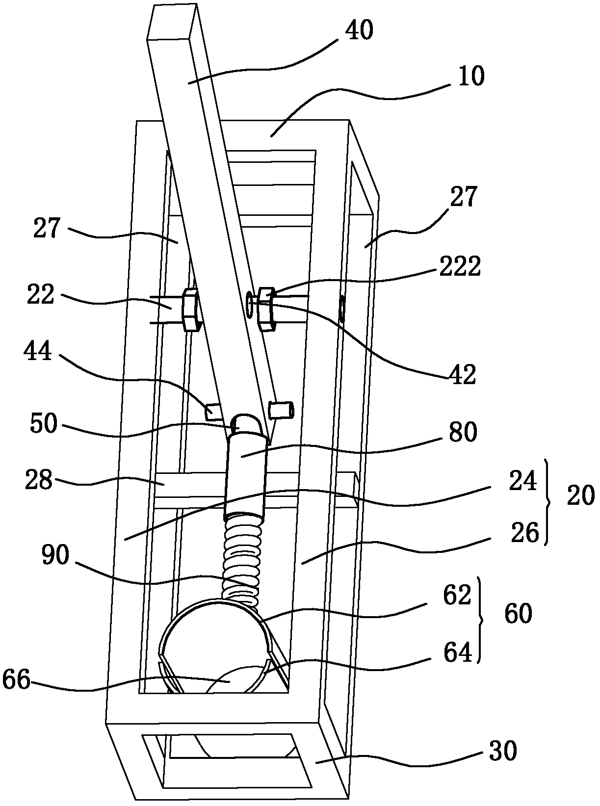
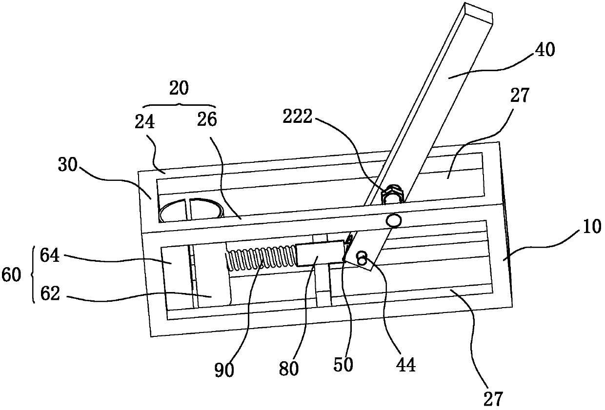
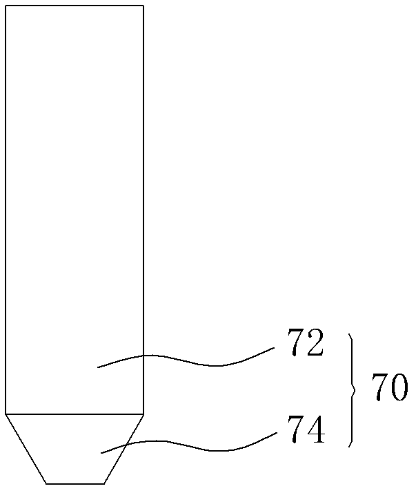
[0030] Please also refer to figure 1 , figure 2 and image 3 , The impact test device of one embodiment, the fixed base frame 10, the support member 20, the clamping base frame 30, the driving rod 40, the pull rod 50, the clamping member 60 and the impact member 70.

[0031] The fixed base frame 10 is used to carry other components of the impact test device and to fix the impact test device to a fixed object or other fixed structure, so as to perform the impact test.

[0032] The supporting member 20 is vertically fixed on the fixed base frame 10 . The support 20 is parallel to the horizontal plane. A support shaft 22 is disposed on the support member 20 . The support shaft 22 is parallel to the ground.

[0033] In t...


PUM

PropertyMeasurementUnit
collision energyaaaaaaaaaa
heightaaaaaaaaaa

Abstract

A shock test device comprises a fixing base frame, strut members, a clamping base frame, a drive rod, a pull rod and a clamping member. The fixing base frame is used for fixing the shock test device to a fixed object; the strut members are parallel to a horizontal plane and are vertically fixed on the fixing base frame; the clamping base frame is vertically fixedly connected with the strut members and is parallel to the fixing base frame; the drive rod is fixed on the middle portion of the strut members through a strut shaft parallel to the ground and can rotate around the strut shaft, and the drive rod is provided with a handle at one end back to the ground; one end of the pull rod is movably connected with the other end of the drive rod through a pin shaft; the clamping member comprises a first clamping part and a second clamping part, and the clamping base frame is fixedly provided with the second clamping part at one side opposite to the fixing base frame; the first clamping part is connected with the other end of the pull rod, and the first clamping part moves with the pull rod to form an open state and a closed state with the second clamping part; a shock member is champed by the first clamping part and the second clamping part. The shock member can be accurately positioned by the clamping member, so that the shock member can accurately shock a sample to be tested, and the accuracy is improved.

Description

【Technical field】 [0001] The invention relates to an impact test device, in particular to an impact test device for explosion-proof lamps. 【Background technique】 [0002] Most products in daily life or industrial applications are usually subjected to impact tests after assembly. The impact test is a test for testing the ability of a product or specimen to withstand impact loads. Generally, it is a test method to determine the safety, reliability and effectiveness of the product when subjected to external force impact or action. [0003] For example, in the field of lighting technology, the impact of the shell of the lamp directly affects the protection level of the shell of the lamp and the safety performance of the lamp, especially for explosion-proof lamps, the impact resistance of the shell is very important for the safe use of explosion-proof lamps. Therefore, whether the explosion-proof lamp can detect the weak point of the lamp shell through the impact test is an imp...

Claims


Application Information

Patent Timeline
Patent Type & Authority Applications(China)
IPC IPC(8): G01N3/303G01M7/08
Inventor 周明杰胡波
Owner OCEANKING DONGGUAN LIGHTING TECH
Why Eureka
Try Eureka