Optical disk, format processing method for the same, recording method for the same, and optical disk device

Technology of a processing method and a recording method, applied in the fields of optical disc devices and optical discs

Inactive Publication Date: 2013-09-25
HITACHI CONSUMER ELECTRONICS CORP
View PDF3 Cites 2 Cited by
  • Summary
  • Abstract
  • Description
  • Claims
  • Application Information

AI Technical Summary

Problems solved by technology

In the abstract of Patent Document 1, the technical problem is described as "to provide an information recording medium capable of preventing loss of data from being destroyed due to detracking of an optical beam without reducing the recording capacity of user data"

Method used


Image

  • Optical disk, format processing method for the same, recording method for the same, and optical disk device
  • Optical disk, format processing method for the same, recording method for the same, and optical disk device
  • Optical disk, format processing method for the same, recording method for the same, and optical disk device

Examples


Embodiment 1

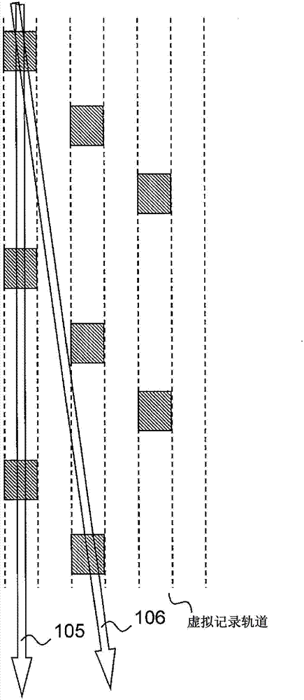
[0055] This embodiment considers the situation that recording cannot be performed under track tracking parallel to the recorded track due to different adjustment values ​​such as warp adjustment and lens shift adjustment in different loading recording operations of the grooveless optical disc. By defining this area as the guidance area, it is always possible to track the track parallel to the target track.

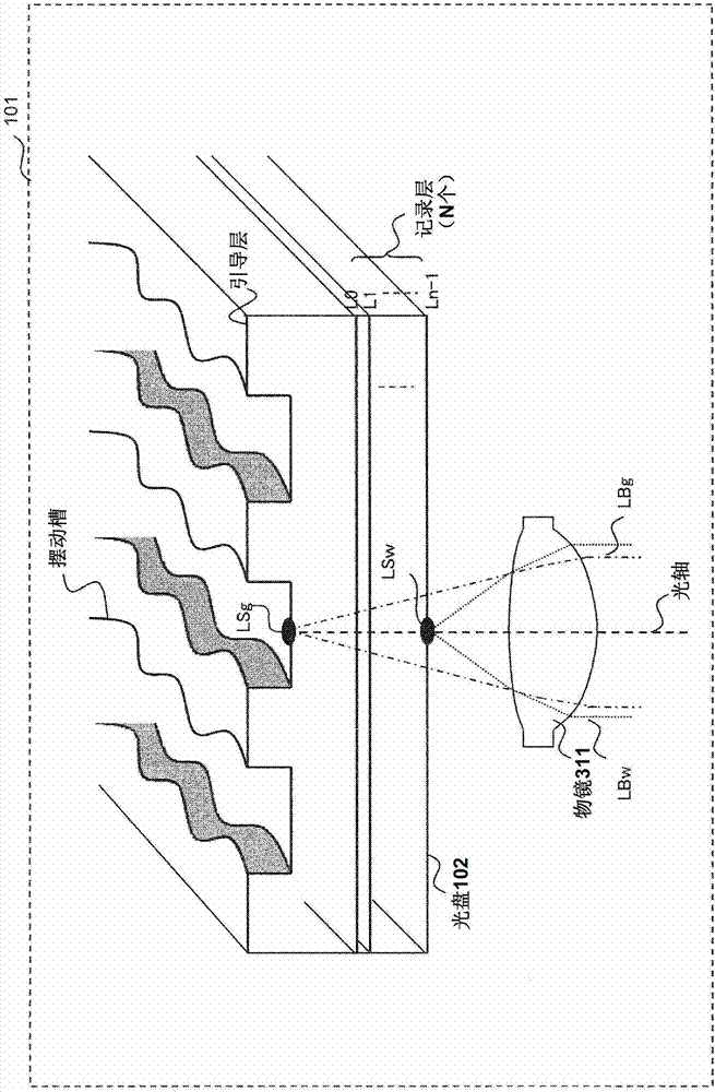
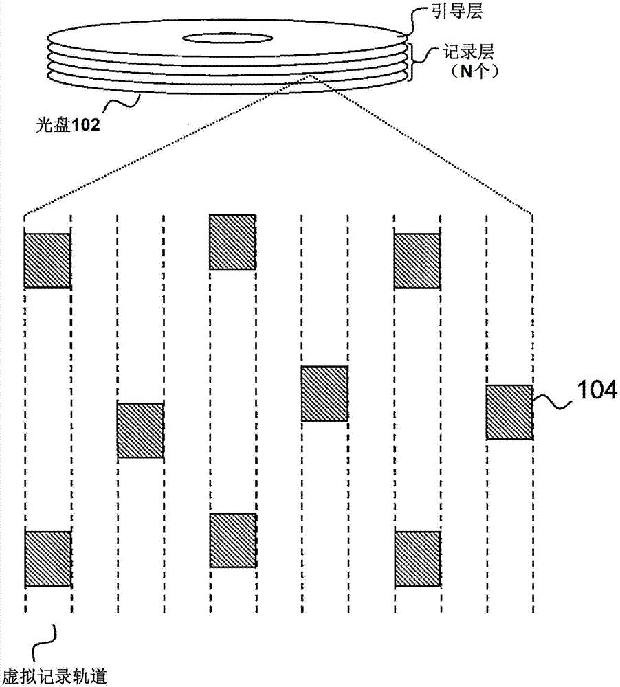
[0056] figure 1 The structure of the optical disc 102 used in this embodiment is shown as an example.

[0057] The optical disc 102 includes a guide layer having a track (guide groove) structure, and N recording layers (N≧1, N is a natural number) not having a track structure. The optical disc device 101 uses the objective lens 311 to generate laser spots LSw and LSg on the recording layer and the guide layer, respectively. In order to perform tracking control of the laser spots LSw and LSg, spiral continuous grooves are formed on the guide layer.

[0058] In the optica...

Embodiment 2

[0135] Figure 10 A processing flowchart showing the recording operation of the second embodiment of the present invention.

[0136] In step S1001, seek to a recording target address for recording. In step S1002, playback is performed from the lead area where the target address is recorded to the next lead area. In step S1003, it is determined whether or not the address values ​​of the lead area are consecutive.

[0137] If the address values ​​are discontinuous, then in step S1004, warpage adjustment and other adjustments are performed again, and the process returns to step S1001 to track the recording target address. If the address value of the lead area is continuously reproduced, the recording target address is returned in step S1005, and the recording is started in step S1006.

[0138]Finally, in step S1007, it is determined whether (the current address) is the recording end address, and if not, return to step S1001 to confirm the next boot area. In the case of an opt...

Embodiment 3

[0141] In this embodiment, an example will be described in which the boot area is not recorded at the time of formatting, and the boot area is simultaneously recorded during the user data recording process.

[0142] Figure 11 Shows the format processing flow of the third embodiment of the present invention.

[0143] In step S1101, it is confirmed whether the address before the recording start address has been recorded, if it is recorded, then in step S1102, the address is tracked to the address before the recording start address, and in step S1103, the guide area at a predetermined interval is reproduced. In step S1104, it is determined whether the address values ​​of the lead area are continuous. If the address values ​​are discontinuous, then in step S1105, warpage adjustment and other adjustments are performed again, and the method returns to step S1102 to track to the address before the start address. If the address values ​​of the boot area are continuously reproduced,...


PUM


Abstract

An optical disk that enables a laser beam to be focused on an object track without making mistakes, an optical disk device, a format processing method, and a recording method. The optical disk shall be configured to has a guiding layer with a physical groove structure containing address information and a single or multiple recording layers with no groove structure, in which the guide areas for recording the address information thereon are formed along a track of the guide layer at fixed intervals in a user data area of each recording layer. An address for the recording layer is generated based on information obtained from the guide layer, and the address for the recording layer is recorded in the guide area.

Description

technical field [0001] The present invention relates to an optical disc, an optical disc device for reproducing information from the optical disc or recording information on the optical disc using laser light, a format processing method, and a recording method. Background technique [0002] As a background art, for example, Patent Document 1 (Japanese Unexamined Patent Application Publication No. 2002-245636) can be cited. In the abstract of Patent Document 1, the technical problem is described as "provide an information recording medium capable of preventing loss of data from being destroyed due to beam derailment without reducing the recording capacity of user data". In addition, the technical means for solving the problem is described as "the information recording medium (1) has: a recording track (#n+1, #n, #n-1) on which a plurality of address information is recorded. The address area (2) of the address area, and a plurality of mark areas (3) with mark information that...

Claims


Application Information

Patent Timeline
Patent Type & Authority Applications(China)
IPC IPC(8): G11B7/2403G11B20/12G11B7/004G11B7/09
CPCG11B7/24038G11B7/00745G11B7/0956G11B7/2405G11B2007/0013G11B7/007
Inventor 井泽信介平林正幸
Owner HITACHI CONSUMER ELECTRONICS CORP
Why Eureka
Try Eureka