High-shielding signal line

A technology for shielding signals and shielding layers, which is applied in the field of high-shielded signal lines, can solve the problems of poor signal line shielding effect and poor high-frequency signal transmission effect, and achieve the effect of good shielding performance.

Inactive Publication Date: 2013-09-25
TIANCHANG FUXIN ELECTRONICS
View PDF4 Cites 0 Cited by
  • Summary
  • Abstract
  • Description
  • Claims
  • Application Information

AI Technical Summary

Problems solved by technology

[0002] At present, there is a plug connected to the audio equipment at both ends of the signal line used for the connection between home audio and CD players. There are terminals at both ends of the plug. A cylindrical conductor is arranged inside the terminal, and a cylindrical conductor is covered with a round tubular conductor. , the cylindrical conductor and the round tubular conductor are fixed by an insulating filling layer, the two sets of cylindrical conductors of the two terminals are connected by wires, and the two round tubular conductors are connected by wires. The above signal lines exist The shielding effect is poor, and the transmission effect of high-frequency signals is poor, which needs to be improved urgently

Method used


Image

  • High-shielding signal line
  • High-shielding signal line
  • High-shielding signal line

Examples


Embodiment 1

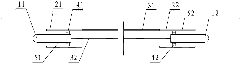
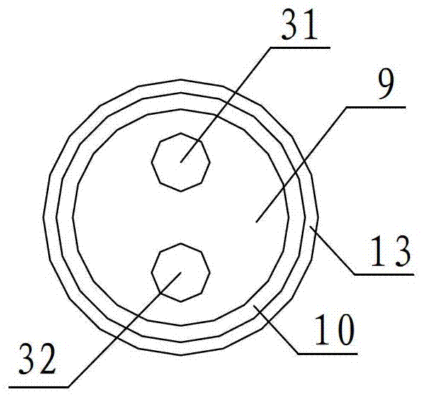
[0019] A high-shield signal line is proposed, which includes a first connection terminal, a first inner conductor 11, a first outer conductor 21, the first inner conductor 11 is sleeved in the first outer conductor 21, and the first inner conductor 21 is connected to the first outer conductor 21. The outer conductors 21 are fixed by the first insulating layer 41; the second connecting terminal consists of the second inner conductor 12, the second outer conductor 22, the second inner conductor 12 is sleeved in the second outer conductor 22, and the second The inner conductor 12 and the second outer conductor 22 are fixed by the second insulating layer 42; the first inner conductor 11 and the second inner conductor 12 are connected by the first connecting wire 31; the first outer conductor 21 and the second outer conductor The conductors 22 are conducted through the second connecting wire 32; the first connecting wire 31 and the second connecting wire 32 are accommodated in the f...


PUM


Abstract

The invention discloses a high-shielding signal line which comprises a first connection terminal and a second connection terminal. The first connection terminal is composed of a first inner conductor and a first outer conductor, the first inner conductor is connected in the first outer conductor in a sleeved mode, and the first inner conductor and the first outer conductor are fixed through a first insulation layer. The second connection terminal is composed of a second inner conductor and a second outer conductor, the second inner conductor is connected in the second outer conductor in a sleeved mode, and the second inner conductor and the second outer conductor are fixed through a second insulation layer. The first inner conductor is communicated with the second inner conductor through a first connecting line, and the first outer conductor is communicated with the second outer conductor through a second connecting line. The first connecting line and the second connecting line are contained in a first shielding layer, and the first insulation layer wraps the first shielding layer. The first connecting line and the second connecting line respectively comprise a conductor layer, a second shielding layer wrapping the conductor layer and a second insulation layer wrapping the second shielding layer. The high-shielding signal line has good shielding performance.

Description

technical field [0001] The invention relates to a high shielding signal line. Background technique [0002] Both ends of the signal line used for the connection between home audio and CD players have a plug connected to the audio equipment. Both ends of the plug are provided with terminals, and a cylindrical conductor is arranged inside the terminal. The cylindrical conductor is covered with a round tubular conductor. , the cylindrical conductor and the round tubular conductor are fixed by an insulating filling layer, the two sets of cylindrical conductors of the two terminals are connected by wires, and the two round tubular conductors are connected by wires. The above signal lines exist The shielding effect is poor, and the transmission effect of high-frequency signals is poor, which needs to be improved urgently. Contents of the invention [0003] In view of the problems existing in the prior art, the purpose of the present invention is to provide a highly shielded sig...

Claims


Application Information

Patent Timeline
IPC IPC(8): H01B7/17
Inventor 林文树林文禄王平贵
Owner TIANCHANG FUXIN ELECTRONICS
Why Eureka
Try Eureka