Crosslinked polyethylene insulated copper wire copper strip shielding frequency converter cable

A cross-linked polyethylene, copper tape shielding technology, applied in the direction of power cables with shielding layer/conductive layer, etc., can solve the problems of high-frequency pulse current breakdown, etc., and achieve good shielding performance and the effect of not being easily interfered by electromagnetic waves

Inactive Publication Date: 2014-10-15
JIANGSU YUANHONG CABLE
View PDF5 Cites 0 Cited by
  • Summary
  • Abstract
  • Description
  • Claims
  • Application Information

AI Technical Summary

Problems solved by technology

[0002] With the intensification of competition in the market economy, energy saving and consumption reduction are imperative for the cable industry to meet its own development needs. The frequency converters that came out in the early 1980s have many advantages such as low noise, long life, small size, large capacity, and energy saving. The advantages are widely used in metallurgy, electric power, petrochemical, textile and other fields. The frequency conversion cable used as the frequency conversion current and the connection line o

Method used


Image

  • Crosslinked polyethylene insulated copper wire copper strip shielding frequency converter cable

Examples


Embodiment 1

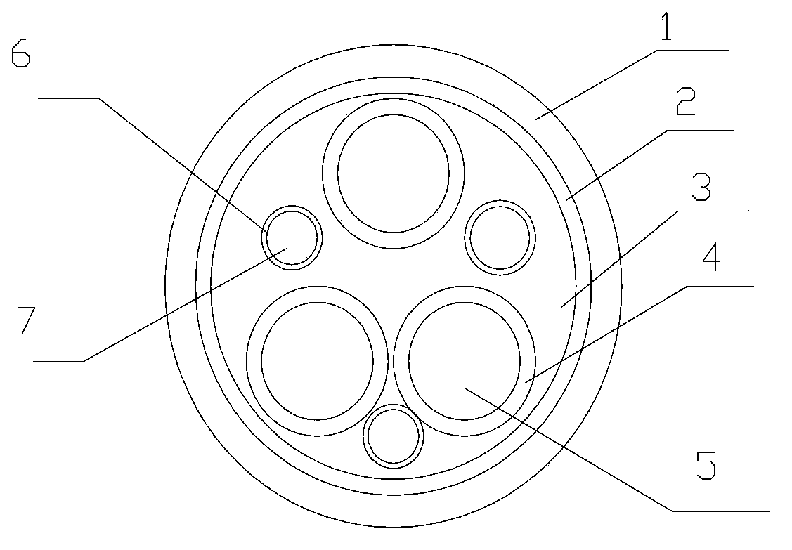
[0013] Embodiment 1: as figure 1 Its structure is shown: a cross-linked polyethylene insulated copper wire copper tape shielded inverter cable, including a cable core, a copper wire shielding layer 5 wrapped around the cable core, a copper wire shielding layer 5 wrapped with a shielding layer 6, and an outer sheath The sheath layer 7 is on the outside of the shielding layer 6, and the cable core is composed of a main conductor 1, an insulating layer I2, a secondary conductor 3, and an insulating layer II4, respectively. There are 3 groups of the main conductor 1 and the secondary conductor 3, showing a 3+3 structure. Symmetrically distributed, the material is a copper conductor, the secondary conductor 3 is symmetrically distributed on both sides of the main conductor 1, the copper wire shielding layer 5 is made of braided copper wire, and the shielding layer 6 is made of T2 calendered copper tape with a thickness of 1.2mm and insulation Layer Ⅰ2 and insulating layer Ⅱ4 are ma...

Embodiment 2

[0014] Embodiment 2: as figure 1 Its structure is shown: a cross-linked polyethylene insulated copper wire copper tape shielded inverter cable, including a cable core, a copper wire shielding layer 5 wrapped around the cable core, a copper wire shielding layer 5 wrapped with a shielding layer 6, and an outer sheath The sheath layer 7 is on the outside of the shielding layer 6, and the cable core is composed of a main conductor 1, an insulating layer I2, a secondary conductor 3, and an insulating layer II4, respectively. There are 3 groups of the main conductor 1 and the secondary conductor 3, showing a 3+3 structure. Symmetrically distributed, the material is a copper conductor, the secondary conductor 3 is symmetrically distributed on both sides of the main conductor 1, the copper wire shielding layer 5 is made of braided copper wire, and the shielding layer 6 is made of T2 calendered copper tape with a thickness of 1.8mm and insulation Layer Ⅰ2 and insulating layer Ⅱ4 are ma...


PUM

PropertyMeasurementUnit
Thicknessaaaaaaaaaa
Thicknessaaaaaaaaaa
Thicknessaaaaaaaaaa

Abstract

A crosslinked polyethylene Insulated copper wire copper strip shielding frequency converter cable comprises a cable core, a copper wire shielding layer wrapped on the cable core, a shielding layer wrapped on the copper wire shielding layer and an outer sheath layer arranged outside the shielding layer. Main conductors, an insulating layer I, secondary conductors and an insulating layer II are extruded to form the cable core, secondary conductors are symmetrically distributed at the two sides of the main conductors, and copper wires are woven and lapped to form the copper wire shielding layer. The crosslinked polyethylene insulated copper wire copper strip shielding frequency converter cable in the invention is not liable to strike through by a high frequency pulse current, and has good shielding performance and is less susceptible to electromagnetic wave interference.

Description

technical field [0001] The invention relates to a power cable, in particular to a cross-linked polyethylene insulated copper wire copper tape shielded inverter cable. Background technique [0002] With the continuous intensification of market economic competition, the cable industry needs to save energy and reduce consumption for its own development needs. The inverters that came out in the early 1980s have many advantages such as low noise, long life, small size, large capacity, and energy saving. The advantages are widely used in metallurgy, electric power, petrochemical, textile and other fields. The frequency conversion cable used as the frequency conversion current and the connection line of the frequency converter will be affected by the high-order harmonics generated by the frequency converter when the frequency converter is working. The current frequency converter on the market Most cables have a 3+1 structure. When high-order harmonics are generated, after multiple ...

Claims


Application Information

Patent Timeline
IPC IPC(8): H01B9/02
Inventor 朱建刚钱涛
Owner JIANGSU YUANHONG CABLE
Why Eureka
Try Eureka