Arc-control device comprising controllable switch and arc-control method of direct-current mechanical switch
A technology of mechanical switches and arc extinguishing devices, which is applied in the direction of electric switches, electrical components, circuits, etc., can solve the problems of large size, inconvenient promotion and popularization of professional DC switches, and high price
- Summary
- Abstract
- Description
- Claims
- Application Information
AI Technical Summary
Problems solved by technology
Method used
Image
Examples
Embodiment 1
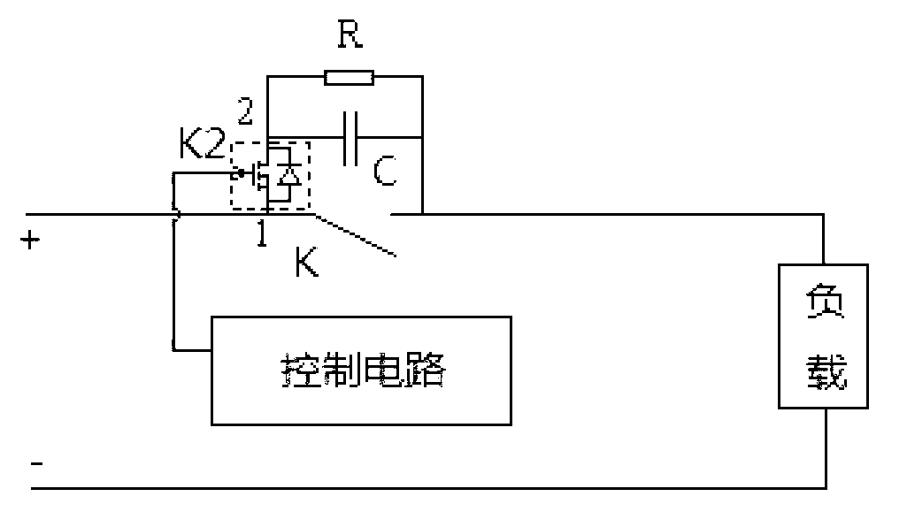
[0034] Embodiment 1: The DC mechanical switch is installed on the positive line side of the DC power supply line
[0035] Such as figure 1 As shown, it is a circuit diagram, in which K represents a DC mechanical switch, and RC in parallel forms an absorption circuit; the switch K2 and the control circuit together form a controllable switch, and the one-way conduction or two-way conduction state of K2 is controlled by the control circuit. figure 1 , the one-way conduction state of the controllable switch is: the one-way conduction state from 1 to 2.
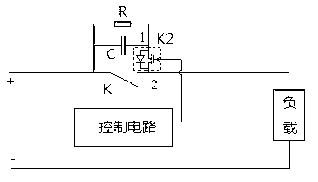
[0036] Such as figure 2 As shown, it is another circuit diagram, which is the same as figure 1 The difference is that the installation position of the controllable switch is slightly different, and the one-way conduction state of the controllable switch is still: one-way conduction state from 1 to 2.
Embodiment 2
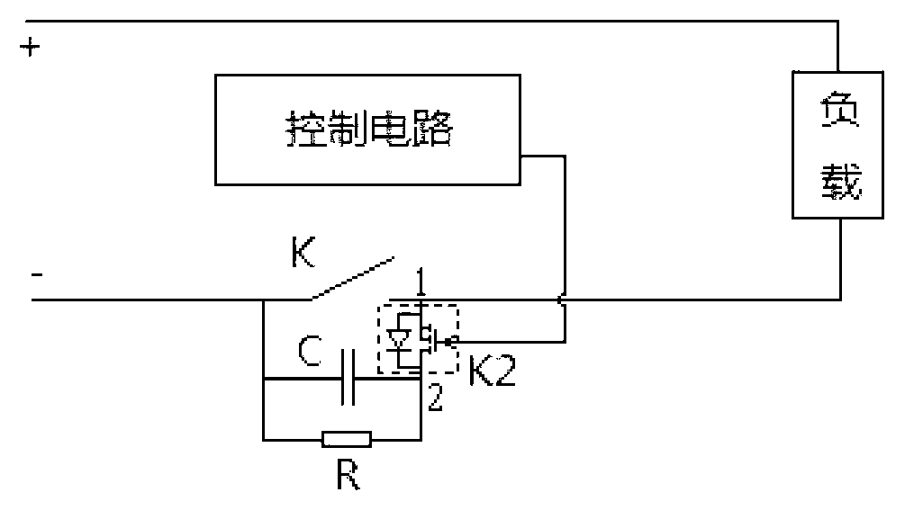
[0037] Embodiment 2: The DC mechanical switch is installed on the negative line side of the DC power supply line
[0038] image 3 and Figure 4 Circuit diagram for two types of DC mechanical switches installed on the negative side. The meanings of the symbols are the same as those in Embodiment 1, and will not be repeated here.
Embodiment 3
[0039] Embodiment 3: DC mechanical switches are respectively installed on the positive line side and the negative line side of the DC power supply line
[0040] Specifically, such as Figure 5 As shown, the DC mechanical switch includes a first DC mechanical switch K1 and a second DC mechanical switch K3; the first DC mechanical switch K1 is installed on the positive line side of the DC power supply line, and the second DC mechanical switch K3 is installed on the DC power supply line negative line side.
[0041]The absorbing circuit 1 and the controllable switch 1 are connected in parallel at both ends of the first DC mechanical switch K1, and the absorbing circuit 2 and the controllable switch 2 are connected in parallel at both ends of the second DC mechanical switch K3. Among them, the installation method of the absorption circuit 1 and the controllable switch 1 and figure 1 or figure 2 Same, the installation method of absorbing circuit 2 and controllable switch 2 and ...
PUM
 Abstract
Description
Claims
Application Information
 - R&D
- Intellectual Property
- Life Sciences
- Materials
- Tech Scout
- Unparalleled Data Quality
- Higher Quality Content
- 60% Fewer Hallucinations
Browse by: Latest US Patents, China's latest patents, Technical Efficacy Thesaurus, Application Domain, Technology Topic, Popular Technical Reports.
© 2025 PatSnap. All rights reserved.Legal|Privacy policy|Modern Slavery Act Transparency Statement|Sitemap|About US| Contact US: help@patsnap.com


