
Method, device and system achieving data demodulation

A technology of data demodulation and data information, applied in the field of communication, can solve the problems that CoMP technology cannot obtain enhanced uplink transmission efficiency, interference randomization design, and cannot realize transmission orthogonality, so as to improve performance and improve data demodulation performance Effect

Active Publication Date: 2013-09-25
HUAWEI TECH CO LTD
View PDF4 Cites 6 Cited by
  • Summary
  • Abstract
  • Description
  • Claims
  • Application Information

AI Technical Summary

Problems solved by technology

The most effective way to reduce the interference received by UEs when sending RSs is to make the RSs sent by all UEs orthogonal to each other, that is, to realize the orthogonalization of RSs; however, in the existing application process, a UE is usually only served by one cell. Since the network-side equipment corresponding to a cell cannot know the RS allocated by other cells for its UE, it is impossible to realize RS orthogonalization in the true sense; Hopping, sequence hopping or CS (Cyclic Shift, cyclic shift) hopping and other ways to randomize the interference between RSs sent by different UEs
[0004] However, with the development of technology, in view of the problem that a UE is usually only served by one cell, CoMP (Coordinated Multiple Point transmission / reception, Coordinated Multiple Point transmission / reception) technology has also emerged, that is, a UE can be served by multiple In this way, the efficiency of uplink transmission can be enhanced; however, due to the limitation of interference randomization design in the prior art, the parameters used by UEs from multiple cells to generate RS are often different, which leads to this problem. This CoMP technology still cannot realize that UEs from different cells send orthogonal RSs, so that the CoMP technology cannot obtain its due effect of enhancing uplink transmission efficiency

Method used


Image

  • Method, device and system achieving data demodulation
  • Method, device and system achieving data demodulation
  • Method, device and system achieving data demodulation

Examples


Embodiment Construction

[0027] The technical solutions in the embodiments of the present invention will be clearly and completely described below in conjunction with the accompanying drawings in the embodiments of the present invention. Obviously, the described embodiments are only some, not all, embodiments of the present invention. Based on the embodiments of the present invention, all other embodiments obtained by persons of ordinary skill in the art without creative efforts fall within the protection scope of the present invention.

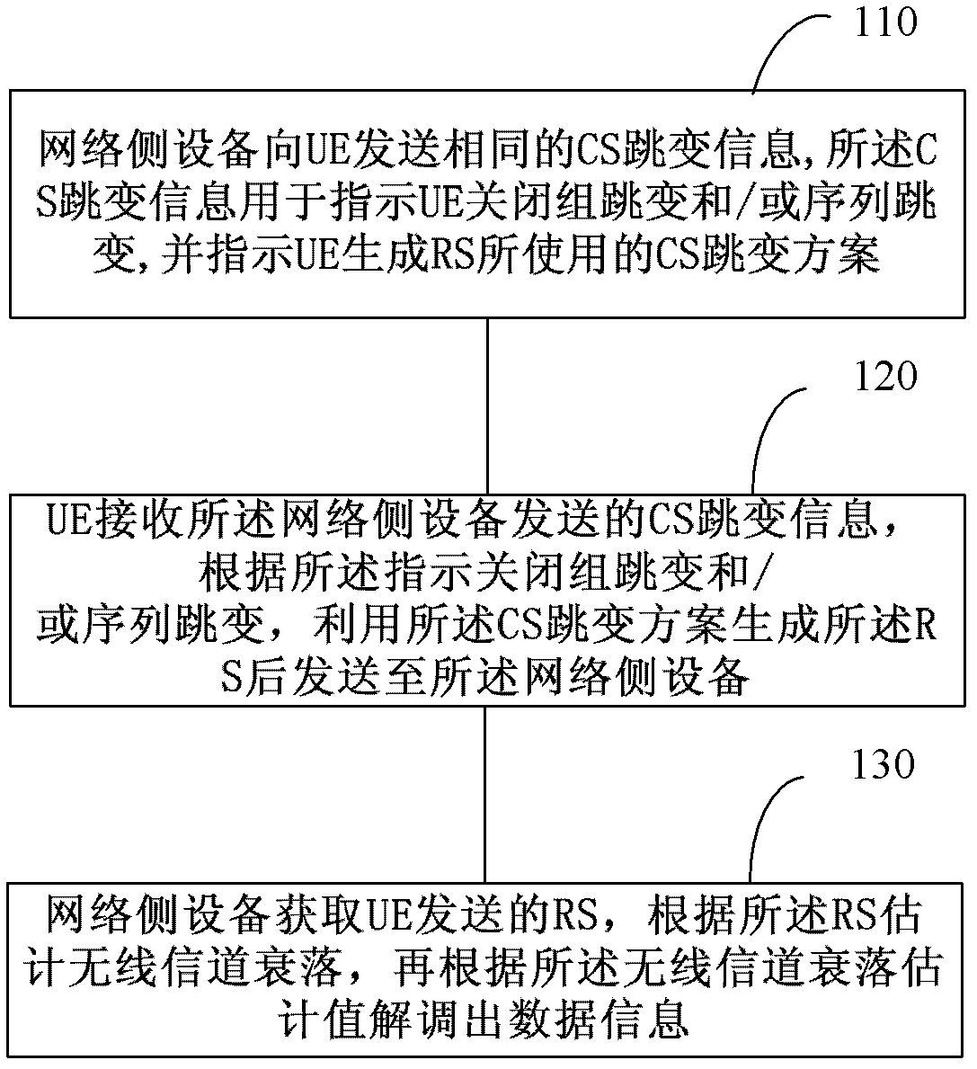
[0028] An embodiment of the present invention provides a method for realizing data demodulation, such as figure 1 As shown, the method includes:

[0029] Step 110: The network side device sends the same CS hopping information to the UE, the CS hopping information is used to instruct the UE to turn off the group hopping and / or sequence sequence, and to indicate the CS hopping scheme used by the UE to generate the RS; wherein , it is worth noting that according to sys...


PUM


Abstract

The invention discloses a method, device and system achieving data demodulation. The method achieving data demodulation comprises the following steps that same cyclic shift hopping information is transmitted to user equipment, and the cyclic shift hopping information is used for indicating the user equipment to close group hopping and / or sequence hopping, and indicates the user equipment to generate a cyclic shift hopping scheme used by a reference signal; the reference signal sent by the user equipment is obtained, wireless channel fading is estimated according to the reference signal, and data information is demodulated according to the estimated value of the wireless channel fading. The method, device and system achieving the data demodulation enables uplink reference signals transmitted by different user equipment to maintain orthogonality mutually, and can further improve data demodulation performance.

Description

technical field [0001] The present invention relates to the field of communication technology, in particular to a method, device and system for realizing data demodulation. Background technique [0002] At present, during the data transmission process, UE (User Equipment, user equipment) will also send RS to the network side device while sending data to the network side device, so that the network side device can use the RS (Reference Signal, refer to signal) to estimate radio channel fading, and then make the network side device use the estimated channel fading to demodulate the data sent by the UE. [0003] Obviously, from this process, it can be seen that the performance of the network side equipment to demodulate the data depends to a large extent on the accuracy of the wireless channel fading estimation, and the accuracy of the wireless channel fading estimation depends on the UE sending The RS, that is, the RS sent by the UE while sending data directly affects the per...

Claims


Application Information

Patent Timeline
IPC IPC(8): H04L25/02H04W72/12
CPCH04L5/003H04J13/0074H04L27/2613H04L27/26136
Inventor 大卫·马瑞泽周明宇
Owner HUAWEI TECH CO LTD
Learn More