Wireless network camera

A wireless network and camera technology, applied in the field of monitoring signal acquisition equipment, can solve the problems of poor real-time performance, inability to obtain on-site monitoring audio/video data, limit the timeliness of wireless network cameras, etc., and achieve the effect of enhancing capabilities

Inactive Publication Date: 2013-09-25
XIAMEN UNIONCORE TECH
View PDF4 Cites 3 Cited by
  • Summary
  • Abstract
  • Description
  • Claims
  • Application Information

AI Technical Summary

Problems solved by technology

[0003] However, the transmission mode of this on-site monitoring signal has the following disadvantages: (1), various terminal devices with network communication functions cannot directly access the wireless network camera through the Internet, and can only obtain those stored in the network from the Internet server through the Internet. The compressed on-site monitoring audio / video data of the wireless network camera in the Internet server, and these data are delayed information, and the real-time performance is not good
(2) Even if various mobile terminals with WiFi functions (such as mobile phones, tablet computers, notebooks, etc.) belong to the same WiFi LAN as the wireless network camera, because the slave devices that belong to the WiFi router in the WiFi LAN, all The wireless network camera cannot be accessed, and the compressed on-site monitoring audio / video data output by the wireless network camera cannot be obtained from the WiFi router
Therefore, the transmission mode of this on-site monitoring signal greatly limits the timeliness of the wireless network camera on-site monitoring application
(3) Even if various mobile terminals (such as mobile phones, tablets, notebooks, etc.) These compressed on-site monitoring audio / video data need to be installed with WiFi hotspot software, etc., to forcibly change the purpose of the mobile terminal, lose the mobile terminal's own WiFi node function, and when the mobile terminal uses its own functions, it will change WiFi hotspot function, lost communication with the wireless IP camera host

Method used


Image

  • Wireless network camera

Examples


Embodiment Construction

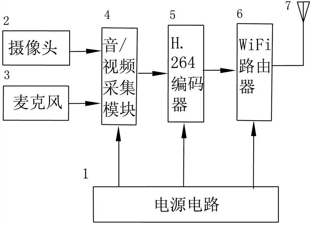
[0008] The circuit structure of an embodiment of the wireless network camera of the present invention, as figure 1 As shown, the wireless network camera has a power supply circuit 1 , a camera 2 , a microphone 3 , an audio / video acquisition module 4 , an encoder 5 , a WiFi router 6 and an external antenna 7 . The power supply circuit 1 supplies power to the audio / video acquisition module 4 , the encoder 5 and the WiFi router 6 . The power supply circuit 1 adopts a battery and is also equipped with a random charging circuit. The signal output ends of the camera 2 and the microphone 3 are respectively connected to the video signal input end and the audio signal input end of the audio / video acquisition module 4 . The video digital signal output end and the audio digital signal output end of the audio / video acquisition module 4 are respectively connected to the video digital signal input end and the audio digital signal input end of the encoder 5 . The encoder 5 adopts a new H.2...


PUM


Abstract

The invention discloses a wireless network camera, and relates to a monitor signal acquisition device, in particular to a device enabling a monitor to acquire signals of the wireless network camera through a wireless network. The wireless network camera comprises a webcam, a microphone, an audio / video acquisition module and an encoder. A signal output port of the encoder is connected with a network signal input port of a WiFi router through a reticle, and a radio wave output end of the WiFi router is connected with an externally-arranged antenna. The wireless network camera can transmit on-site monitoring audio / video data to internet far-end terminal devices and various mobile terminals with WiFi functions in a WiFi local area network in real time.

Description

technical field [0001] The invention relates to a monitoring signal collection device, in particular to a device for a monitor to collect camera signals through a wireless network. Background technique [0002] The existing wireless network camera consists of camera (image sensor), microphone (sound sensor), audio / video acquisition module (A / D converter), encoder (image and sound data compression circuit), WiFi network card and built-in antenna, etc. Partial composition. The on-site scene is converted into an electrical signal of the image by the camera, and the sound of the scene is converted into an electrical signal of the sound by the microphone; the audio / video acquisition module converts the analog electrical signal of the image and sound into a digital electrical signal, and then passes through the encoder according to a certain After the encoding standard is encoded and compressed, the WiFi network card sends it to the built-in antenna according to a certain network...

Claims


Application Information

Patent Timeline
Patent Type & Authority Applications(China)
IPC IPC(8): H04N5/225H04N5/232H04N7/26
Inventor 周宏围
Owner XIAMEN UNIONCORE TECH
Why Eureka
Try Eureka