
Wireless multi-functional periscope type meter reading device

A multi-functional, periscope technology, applied in closed-circuit television systems, etc., can solve problems that affect work efficiency, helpless cleaning work, and potential safety hazards, and achieve convenient operation, improved production efficiency, and convenient meter reading. Effect

Inactive Publication Date: 2013-09-25
STATE GRID CORP OF CHINA +1
View PDF12 Cites 21 Cited by
  • Summary
  • Abstract
  • Description
  • Claims
  • Application Information

AI Technical Summary

Problems solved by technology

Due to the existence of data transmission lines, the entire periscope meter reading device is messy and inconvenient to fold. The data transmission lines are also easy to pull and entangle with surrounding objects during use, which affects work efficiency.
[0004] In addition, because the electric energy meter is usually installed outdoors, the observation window of the electric energy meter box is easily contaminated with dust, which will bring difficulties to the meter reading personnel and cause wrong readings. Therefore, it is necessary to check the electric energy meter from time to time according to the actual situation. observation window for cleaning
Although the existing periscope meter reading device can bring convenience to meter reading, it is not conducive to the smooth progress of the cleaning work. Usually, the observation window of the electric energy meter has to be wiped manually with the help of ladders, stools, etc. Cleaning is labor-intensive, inefficient, and has potential safety hazards

Method used


Image

  • Wireless multi-functional periscope type meter reading device
  • Wireless multi-functional periscope type meter reading device
  • Wireless multi-functional periscope type meter reading device

Examples


Embodiment Construction

[0017] The present invention will be further described below in conjunction with the accompanying drawings and specific embodiments.

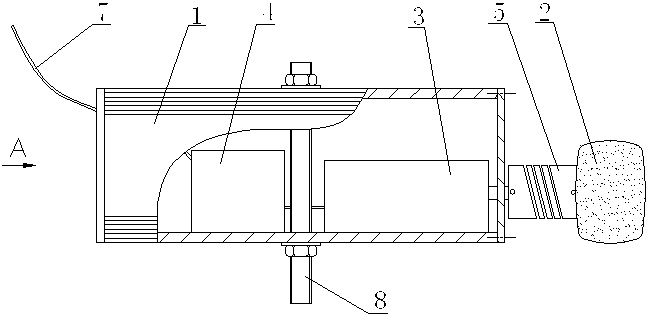
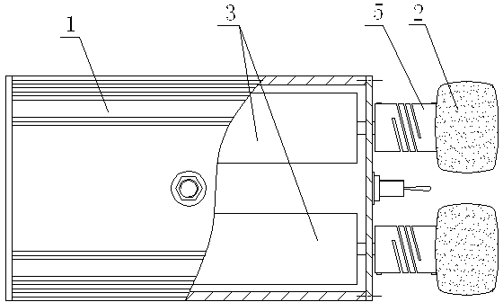
[0018] Such as figure 1 As shown, the wireless multifunctional periscope meter reading device of the present invention contains an insulating telescopic rod 9, a camera 10 and a display terminal 11, and the camera 10 is connected to the top of the insulating telescopic rod 9 by a universal rod 13, and the display terminal 11 is connected to the The lower part of the insulating telescopic rod 9 is connected with the wireless signal between the camera 10 and the display terminal 11 , and a cleaner 12 is also connected to the top of the insulating telescopic rod 9 . Since the wireless signal transmission mode is adopted between the camera 10 and the display terminal 11, the situation that the data transmission line is entangled with the live equipment is avoided, which is convenient for the entire periscope meter reading device to be folded and ca...


PUM


Abstract

The invention discloses a wireless multi-functional periscope type meter reading device which comprises an insulation telescopic rod, a camera and a display terminal. The camera is connected at the top end of the insulation telescopic rod through a universal rod. The display terminal is connected on the lower portion of the insulation telescopic rod. The camera is connected with the display terminal through wireless signals. A sweeper is further connected at the top end of the insulation telescopic rod. The sweeper is provided with a box-shaped outer shell and a cleaning head. A motor and a control circuit board are arranged in the box-shaped outer shell. An output shaft of the motor horizontally extends out of one end of the box-shaped outer shell and is connected with the cleaning head through a connecting shaft. Charging insertion holes are formed in the other end face of the box-shaped outer shell and a signal receiving antenna educed from the control circuit board is arranged on the other end face of the box-shaped outer shell. A bolt is perpendicularly arranged in the middle of the lower end face of the box-shaped outer shell. The wireless multi-functional periscope type metering device brings convenience to meter reading work, has the function of sweeping a view window of an electric energy meter, enables sweeping and meter reading to be completed one time, is convenient to operate and safe, saves labor, and improves the efficiency of production operation.

Description

technical field [0001] The invention relates to a meter reading device, especially a periscope type meter reading device. Background technique [0002] In the power line, due to the objective conditions of the meter installation position, some electric energy meters will be installed at a relatively high position. inconvenient. For these high-position electric energy meters, the traditional method is to use ladders, stools and other climbing tools to read the meters. The modern method is to use periscope meter reading devices. The camera at the top of the pole takes pictures of the energy meter display and transmits the image to the display terminal, where the data is indirectly read to complete the meter reading work. [0003] At present, the commonly used periscope meter reading device is wired transmission, that is, the image captured by the camera is transmitted to the display terminal through a wired method. Due to the existence of the data transmission line, the who...

Claims


Application Information

Patent Timeline
Patent Type & Authority Applications(China)
IPC IPC(8): H04N7/18
Inventor 段锴李志勇周勇杨云莹黄宇翔胡永张踽顾博李伟蒋贞贤刘俸邑刘科马科王娜黄海波樊洋利曹能邓丁华陈渠袁冲朱鹂
Owner STATE GRID CORP OF CHINA
Learn More