Intelligent controller used for public lighting facilities

A technology for intelligent controllers and lighting facilities, applied in energy-saving control technology, lighting devices, light sources, etc., can solve problems such as long-burning lights, waste of natural resources, and troublesome management of lighting facility switches, and achieve the effect of saving electricity

Inactive Publication Date: 2013-09-25
XIANGFAN UNIVERSITY
0 Cites 0 Cited by

AI-Extracted Technical Summary

Problems solved by technology

[0002] In many public places, lighting facilities will be installed and used, but some public places will be in a state of no o...

Abstract

The invention provides an intelligent controller used for public lighting facilities. A combined relay alternating current contactor provided with a wire head used for external connection is connected with an input terminal of a microcomputer photosensitive timer, an output terminal of the microcomputer photosensitive timer is connected with a relay coil J, a contact switch, a crystal diode, a resistor R, and a photoelectric diode through conducting wires, and is connected with a combined relay alternating current contactor coil at the same time; and the output terminal of the microcomputer photosensitive timer is further connected with a transformer, a rectifier, an electrolytic capacitor, a diode, the relay coil J, a crystal triode, and another diode. The public lighting facility intelligent controller can be used in cooperation with the lighting facilities, and is capable of presetting electricity service time limit in a using process, so that an aim of realizing intelligent control of switching on and off in manners of timing control and photosensitive regulation can be achieved, and electricity saving and public facility management are facilitated.

Application Domain

Electric light circuit arrangementEnergy saving control techniques

Technology Topic

ContactorExternal connection +17

Image

  • Intelligent controller used for public lighting facilities

Examples

  • Experimental program(1)

Example Embodiment

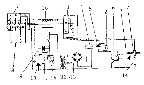
[0012] The embodiment of the drawing shows: the combined relay AC contactor 1 with the external wire head 8 is connected to the input end of the microcomputer photosensitive timer 3, and the output port of the microcomputer photosensitive timer 3 is connected to the relay coil J contact through a wire Switch 16, crystal diode 11, resistor R9 and photodiode 10 are connected to the combined relay AC contactor coil CJ15 at the same time; then connect the transformer 12, rectifier bridge 13, electrolytic capacitor 4, crystal diode 5, relay coil J2, transistor 6 And another crystal diode 5. The combined relay AC contactor coil CJ15 is provided with a wire connected to the combined relay AC contactor 1. The relay coil J contact switch 16 is provided with a wire connected to the relay coil J2, and the resistor 7 and the photosensitive resistor 14 form a loop with the rectifier bridge 13.
[0013] The working process of the lighting intelligent controller: preset the switch time limit of the microcomputer photosensitive timer 3 for electricity consumption every night, the lighting intelligent controller works normally, and the lighting appliances are used normally. When the rainy day comes, the light will drop. Although it is not within the preset power time limit, the microcomputer photosensitive timer 3 is turned on immediately. At the same time, the resistance value of the photoresistor becomes larger due to the drop of light. The transistor 6 is saturated and turned on, and the relay coil J2 When the power is turned on, the combined relay AC contactor coil CJ15 is turned on to turn on the lighting power supply. When the closing time is reached, the photosensitive timer 3 automatically cuts off the power, and the combined relay AC contactor coil CJ15 cuts off the lighting power. So as to achieve the purpose of intelligent lighting control.
[0014] In application, the three-phase AC power is introduced from the ABCN terminal at the upper end of the combined relay AC contactor 1, from K 1 K 2 K 3 Output on the N terminal to provide power for lighting appliances.

PUM

no PUM

Description & Claims & Application Information

We can also present the details of the Description, Claims and Application information to help users get a comprehensive understanding of the technical details of the patent, such as background art, summary of invention, brief description of drawings, description of embodiments, and other original content. On the other hand, users can also determine the specific scope of protection of the technology through the list of claims; as well as understand the changes in the life cycle of the technology with the presentation of the patent timeline. Login to view more.

Similar technology patents

Method and device for controlling air conditioner

ActiveCN105135606Asave electricity
Owner:TCL AIR CONDITIONER ZHONGSHAN CO LTD

Dynamic frequency conversion device of bus in high speed and kermel interface of processor under SOC architecture

InactiveCN1661576AReasonable use of power consumptionsave electricity
Owner:INST OF COMPUTING TECHNOLOGY - CHINESE ACAD OF SCI

Hybrid bicycle

InactiveCN101607585Asave electricityTransmission effort
Owner:陈戈平 +2

Classification and recommendation of technical efficacy words

  • Save electricity

Double screen notebook computer

InactiveCN1690915Asave electricityProtect personal privacy
Owner:秦建忠

Novel megawatt wind generating set testing system and testing method thereof

InactiveCN101881814Asave electricityFlexible system configuration
Owner:INNER MONGOLIA GEOHO ENERGY EQUIP

Food baking one-key-system control method

InactiveCN103120548Aeasy to usesave electricity
Owner:LG ELECTRONICS (TIANJIN) APPLIANCES CO LTD
Why Eureka
Try Eureka