Tubular beams for automotive structures with improved crash performance

A crossbeam and bumper technology, applied to vehicle components, vehicle safety arrangements, bumpers, etc., can solve problems such as increasing the weight of bumpers, going against market trends, and energy consumption

Active Publication Date: 2016-03-09
CONSTELLIUM SINGEN
View PDF8 Cites 2 Cited by
  • Summary
  • Abstract
  • Description
  • Claims
  • Application Information

AI Technical Summary

Problems solved by technology

These methods, especially the first one, have disadvantages: a significant increase in the weight of the bumper, which goes against current market trends, which makes any solution lead to additional energy consumption

Method used


Image

  • Tubular beams for automotive structures with improved crash performance
  • Tubular beams for automotive structures with improved crash performance
  • Tubular beams for automotive structures with improved crash performance

Examples


Embodiment 1

[0039] Embodiment 1: ( image 3 and Figure 4 , Figure 5 variant)

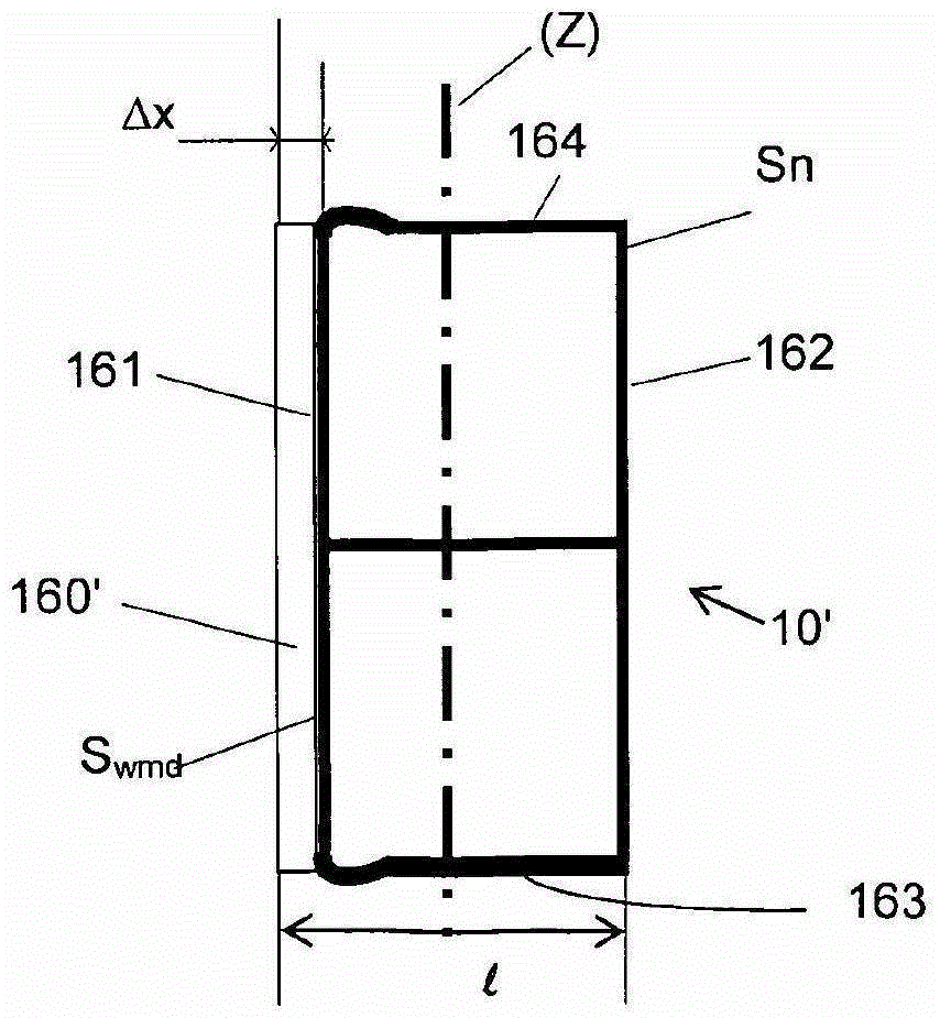
[0040] image 3 and Figure 4 A first embodiment of the invention is shown: the bumper beam (10') is made from an extruded aluminum alloy profile which has been bent to have the intended general shape of the bumper; and the weakened area has passed through the Made by plastic deformation of the front wall. The cross-section of the profile comprises a front wall (161), a rear wall (162), a top wall (164) and a bottom wall (162).

[0041] In the weakened areas (15'a and 15'b), the front wall (161) is pushed towards the bumper by: placing a punch over the entire height of said front wall; and, actuating said punch, so that it moves a distance ΔX towards the profile, creating a depression (160'). In order to obtain a continuous slight change in cross-section in the weakened area to prevent the beam from breaking suddenly in the transition zone, the indenter has a curved working surface with a radius of cur...

Embodiment 2

[0043] Embodiment 2: ( Figure 6 )

[0044] Figure 6 Another embodiment of the invention is shown: the bumper beam (10''') is made from an extruded aluminum alloy profile that has been bent to have the intended general shape of the bumper; and, the weakened area has been passed A front portion of a beam is machined and includes a front wall and portions of top and bottom walls immediately adjacent the front wall. The geometry of the machined surface emulates the recessed bracket-type shape of the first embodiment, with the difference that there is no longer a front wall (161) in the weakened area, so that the recess (160) is replaced by a hole communicating with the interior of the hollow profile ( 17) Instead.

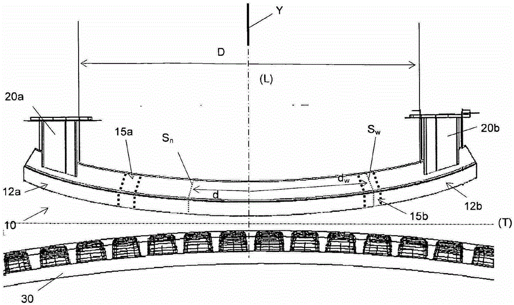
[0045] Depending on the vehicle to be equipped with the bumper, the beam of the bumper is bent with one or more radii of curvature and the distance D between the attachment areas (12a, 12b) is approximately between 1000mm and 2000mm. The weakened area is approxim...


PUM


Abstract

Bumper crossbeam (10, 10'), having a plane of symmetry (Y) and globally oriented in a direction (T) perpendicular to the plane of symmetry (Y), comprising two attachment areas (12a, 12b) symmetrically arranged with respect to the plane of symmetry (Y) and distant from each other by a distance D, said beam being designed to absorb the energy dissipated by a shock generated by a force substantially horizontal and oriented in a direction (L) perpendicular to said direction (T), made from a globally tubular body (11) with a monotonically varying nominal cross-section (Sn) over most of its length between said attachment areas (12a, 12b), except in two weakened areas (15a, 15b), which are symmetrical with respect to the plane of symmetry (Y), which are remote from the said plane of symmetry by a distance of between 0.10*D and 0.40*D, wherein the second moment of area about the axis (Z) perpendicular to the plane (L, T) is lower in the said weakened areas than expected from the nominal cross-section.

Description

technical field [0001] The present invention relates to automotive structural components designed to irreversibly absorb the energy of a crash. The field involved differs from that of energy absorber elements (sometimes referred to as "deformation elements" or "crash boxes") in that the part is not primarily subject to compressive stresses in a crash, but rather bending stress. More specifically, the present invention relates to bumper beams. Background technique [0002] Before the mid-nineties, beams, more specifically bumper beams, designed to irrecoverably absorb energy in a crash, were made from formed sheet metal, usually steel. Increasingly stringent requirements from car manufacturers have led to the insertion of deformable intermediate elements between said beams and longitudinal vehicle supports, known as "absorbers", "crash boxes" or "deformable element". [0003] The bumper beam must both deform elastically during weak impacts and partly absorb the energy of ...

Claims


Application Information

Patent Timeline
IPC IPC(8): B60R19/18B60R19/02
CPCB60R19/18B60R19/02B60R19/023B60R19/03B60R2019/182
Inventor M·库切拉M·费厄斯坦O·瑞布菲特
Owner CONSTELLIUM SINGEN
Why Eureka
Try Eureka