
Analog measuring probe for machine tool equipment and method of operation

A technology for simulating probes and equipment, applied in the field of measuring probes, which can solve problems such as inaccurate measurement and inability of probes to work, and achieve the effect of avoiding overvoltage or undervoltage

Active Publication Date: 2016-08-17
RENISHAW PLC
View PDF11 Cites 0 Cited by
  • Summary
  • Abstract
  • Description
  • Claims
  • Application Information

AI Technical Summary

Problems solved by technology

Failure to seal the probe can result in inaccurate measurements, or even render the probe non-functional at all

Method used


Image

  • Analog measuring probe for machine tool equipment and method of operation
  • Analog measuring probe for machine tool equipment and method of operation
  • Analog measuring probe for machine tool equipment and method of operation

Examples


Embodiment Construction

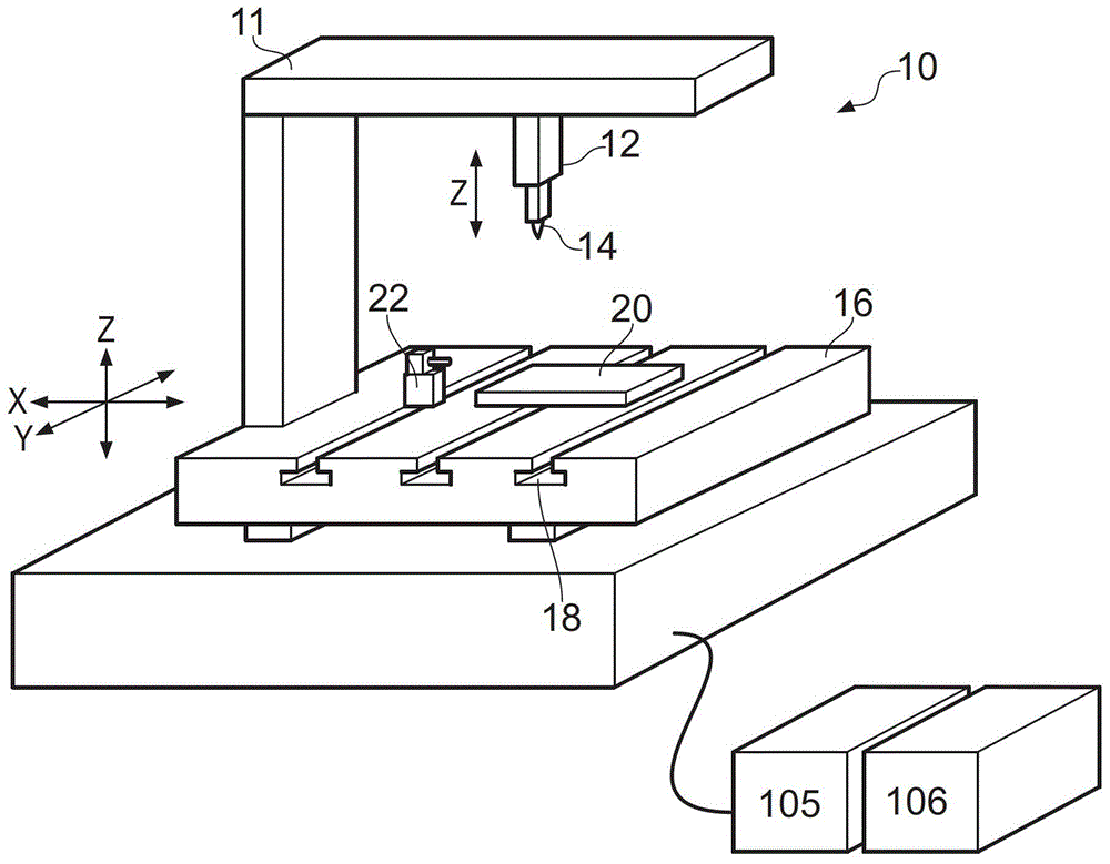
[0094] Reference figure 1 The conventional machine tool equipment 10 includes a bed 16 on which a workpiece 20 and any machine tool accessories such as a tool adjuster 22 can be installed. The machine tool 10 also includes a frame 11 supporting a spindle 12 on which a tool 14 can be mounted.

[0095] The spindle 12 and the machine bed 16 can move relative to each other along three orthogonal directions X, Y, and Z in the working space of the machine tool device 10. In this example, the mandrel 12 and the cutter 14 can move in the Z direction, and the table can move in the X and Y directions. This movement is achieved by X, Y and Z drives (not shown) controlled by the machine tool controller 105 or any suitable computer and interface. A measurement scale reading device (not shown) is provided on each of the respective X, Y, and Z axes in order to measure the relative movement of the mandrel 12 in each direction. Therefore, the mandrel 12 and the bed 16 can accurately move relati...


PUM


Abstract

A simulation probe for machine tool equipment, the simulation probe includes: a probe body; a stylus member movably fixed to the probe body; and a displacement size of the stylus member relative to the probe body for measuring a sensor, wherein the sensor is housed in a chamber in the probe body. The simulation probe further includes a vent located between an exterior of the probe body and the chamber, the vent being configured such that the pressure within the chamber when the vent is open can interact with the operation of the simulation probe Ambient pressure equalization, and is further configured such that the opening of the vent to the exterior of the probe body can be closed thereby removing the chamber, and thus the sensor, from the outside during operation of the analog probe. Contaminant sealing.

Description

Technical field [0001] The invention relates to a measuring probe for use with a coordinate positioning device and an operating method of such an analog probe. In particular, the present invention relates to an analog measuring probe for use with machine tool equipment and an operating method of such an analog probe. Background technique [0002] The analog measurement probe can include a stylus with a stylus tip for contacting the surface of the workpiece. The stylus can protrude from the probe body and can be movably connected to the probe body. The measurement probe can further include a sensor for measuring the movement of the stylus relative to the probe body. The stylus of the analog measuring probe can make contact with the object, so that information about the shape or position of the object can be obtained. In the analog probe, the deflection size (and optional direction) of the stylus can be continuously sensed when the stylus moves along the surface of the workpiece...

Claims


Application Information

Patent Timeline
Patent Type & Authority Patents(China)
IPC IPC(8): G01B5/012G01B7/00G01B7/012G05B19/404
CPCG01B5/012G01B7/016G01B7/00G01B7/012G05B19/182
Inventor 大卫·科林伍德约翰·罗伯特·布拉格
Owner RENISHAW PLC
Features
  • Generate Ideas
  • Intellectual Property
  • Life Sciences
  • Materials
  • Tech Scout
  • Unparalleled Data Quality
  • Higher Quality Content
  • 60% Fewer Hallucinations
Learn More