Dynamic image coding device and dynamic image coding method

A technology for dynamic images and encoding devices, which is applied in image communication, digital video signal modification, electrical components, etc., can solve the problems of large worst-case entropy encoding delay, not meeting the operation requirements of receiving buffers, etc., and achieve the effect of reducing delay.

Inactive Publication Date: 2016-10-05
FUJITSU LTD
View PDF6 Cites 0 Cited by
  • Summary
  • Abstract
  • Description
  • Claims
  • Application Information

AI Technical Summary

Problems solved by technology

When the encoding device encodes the compressed data of each block according to such an entropy encoding method, there is a possibility that the worst value of the entropy encoding delay becomes very large (for example, 4096 bits)
Furthermore, if the worst value of the entropy encoding delay becomes large, the result may not satisfy the operation specification of the receive buffer in an ideal decoding device.

Method used


Image

  • Dynamic image coding device and dynamic image coding method
  • Dynamic image coding device and dynamic image coding method
  • Dynamic image coding device and dynamic image coding method

Examples


Embodiment Construction

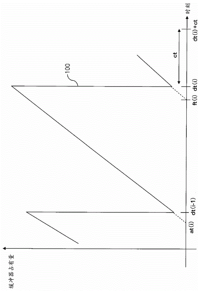
[0037] Hereinafter, a video encoding device according to an embodiment will be described with reference to the drawings. This video coding apparatus classifies blocks included in an image into groups, and adjusts the amount of coding of the blocks included in the group based on the decoding time estimated for each group, thereby reducing decoding delay. Also, the video encoding device corrects the estimated decoding time for each group based on the maximum delay time when entropy encoding the compressed data of each block, and notifies the video decoding device of the corrected estimated decoding time. Accordingly, the video encoding device can prevent the receiving buffer of the video decoding device from underflowing due to delay caused by entropy encoding.

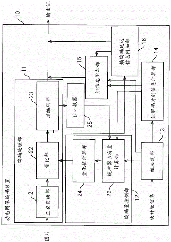
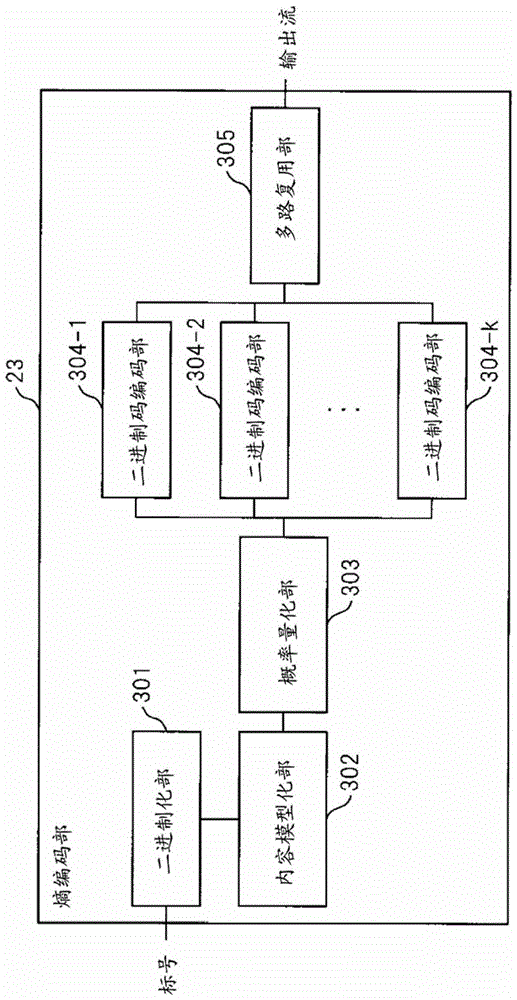
[0038] figure 2 It is a schematic configuration diagram of a video encoding device according to an embodiment. The video encoding device 10 has an encoding processing unit 11 , an encoding amount control unit 12 , a ...


PUM


Abstract

The video encoding device includes: a group determination unit for determining which group among the plurality of groups each of the plurality of blocks after dividing the image belongs to; a group decoding time information calculation unit for calculating the decoding time for each group; The part controls the entropy-encoded encoding amount of the data of each block included in the group when the data required for decoding of all the blocks included in the group is transmitted to the video decoding device at a predetermined transmission rate, so that Arriving at the data stream receiving buffer of the video decoding device before the decoding time of the group; the compression unit compresses the data of each block based on the encoding amount; the entropy encoding unit performs entropy encoding on the compressed data of each block and a decoding information adding unit for adding, to the output data, correction information of decoding time of each group corresponding to a maximum value of delay of each group accompanying entropy encoding and group information indicating a group to which each block belongs.

Description

technical field [0001] The present invention relates to, for example, a video encoding device, a video encoding method, and a computer program for video encoding that divide each image into a plurality of blocks and encode each block. Background technique [0002] Dynamic image data generally has a very large data volume. Therefore, a device that processes video data performs compression by encoding the video data when it intends to transmit the video data to other devices or to store the video data in a storage device. As a representative coding standard for moving pictures, Moving Picture Experts Group phase 2 (MPEG-2), MPEG-4 or H.264MPEG-4 Advanced Video Coding ( MPEG-4AVC / H.264). [0003] In such a coding standard, an interframe coding method for coding a coding target picture using information of the coding target picture and pictures before and after it, and a coding method using only the information held by the coding target picture are adopted. Intra coding metho...

Claims


Application Information

Patent Timeline
Patent Type & Authority Patents(China)
IPC IPC(8): H04N19/149H04N19/124H04N19/91H04N19/152H04N19/174
CPCH04N19/124H04N19/149H04N19/152H04N19/174H04N19/91H04N19/00H04N19/625
Inventor 数井君彦岛田智史中川章三好秀诚小山纯平
Owner FUJITSU LTD
Why Eureka
Try Eureka