
Photoelectric protection type button set-in machine

A technology of photoelectric protection and buttoning machine, which is applied in the direction of mechanical equipment, engineering safety devices, sewing tools, etc., can solve problems such as incoordination of hands and feet, pinch fingers of buttoning machine, increase enterprise operating costs, etc., to prevent Misoperation and the effect of reducing industrial accidents

Inactive Publication Date: 2013-10-02
常熟市海虞镇志宏五金厂
View PDF6 Cites 5 Cited by
  • Summary
  • Abstract
  • Description
  • Claims
  • Application Information

AI Technical Summary

Problems solved by technology

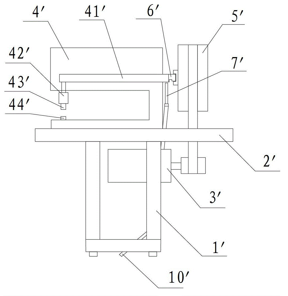
During use, the buttons need to be manually installed on the upper mold base 43' and the lower mold base 44' of the button loading machine. However, the staff is prone to uncoordinated hands and feet during long-term work, which may cause the button loading machine to be pinched. Fingers not only bring physical and mental harm to the staff, but also increase the operating cost of the enterprise
[0003] In order to reduce the probability of industrial accidents, many existing button loading machines have a protective ring between the upper and lower molds. However, installing the protective ring will hinder the placement and installation of buttons and reduce work efficiency.

Method used


Image

  • Photoelectric protection type button set-in machine
  • Photoelectric protection type button set-in machine
  • Photoelectric protection type button set-in machine

Examples


Embodiment Construction

[0018] The present invention will be further described below in conjunction with the embodiments shown in the accompanying drawings.

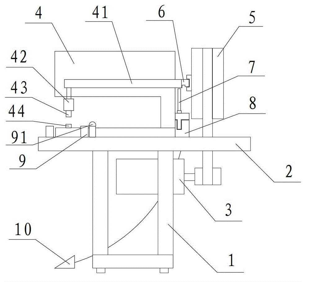
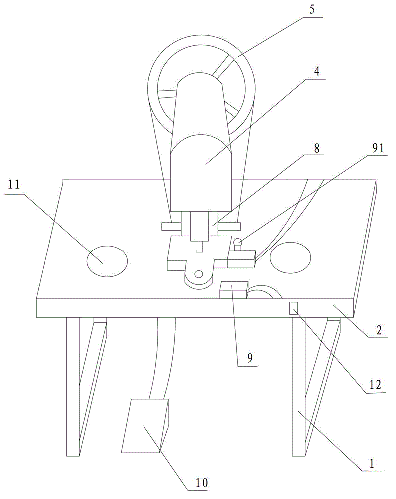
[0019] Such as figure 2 , 3 The shown photoelectric protection button loading machine mainly includes a support frame 1 , a workbench 2 , a motor 3 , a button loading machine body 4 , a transmission mechanism 5 , an electromagnetic module 8 , and a photoelectric induction module 9 . Wherein two support frames 1 are arranged in parallel and are perpendicular to the horizontal plane, the workbench 2 is fixed on the two support frames 1, and the motor 3 is fixed below the workbench 2 to provide power to the button loading machine body 4 through the transmission mechanism 5. The button loading machine body 4 is provided with a main shaft 41, one end of which is connected with the clutch 6, and one end is connected with the stamping head 42. An electromagnetic module 8 is fixed on the workbench 2 below the clutch 6 and is connected with it by a p...


PUM


Abstract

The invention relates to a photoelectric protection type button set-in machine. The photoelectric protection type button set-in machine comprises an electromagnetic module fixed on a work table and connected with a pull rod, a photoelectric sensing module installed beside a button set-in machine body and on the same side as the hand placing a button upper die, and a foot switch placed on the ground. The photoelectric sensing module, the foot switch and the electromagnetic module are sequentially connected for forming a switch circuit. According to the photoelectric protection type button set-in machine, the photoelectric sensing module and the foot switch are arranged at the same time and control the electromagnetic module together, when one of the photoelectric sensing module and the foot switch is in the disconnected state, the electromagnetic module cannot work, so that misoperation by working personnel during the long-time work process is prevented effectively, and the industrial accidents are reduced.

Description

technical field [0001] The invention relates to a button loading machine, in particular to a photoelectric protection type button loading machine. Background technique [0002] The button loading machine is mainly used for metal buttons, decorative buttons, H-shaped buttons, and air holes. It is widely used in garment factories and leather bag processing enterprises. It is suitable for all kinds of clothing, knitted garments, down jackets, and denim clothing. , shoes and hats and leather, plastic, canvas products, various metal snap buttons, craft buttons, denim buttons and rivets, springs, snap buttons, shoe rivets, etc. Such as figure 1 As shown, the existing button loading machine includes a support frame 1' arranged in parallel and perpendicular to the horizontal plane, a workbench 2' fixed on the support frame 1', a motor 3' fixed under the workbench 2', a motor 3' fixed on the workbench The button-loading machine body 4' on the platform 2', the main shaft 41' located...

Claims


Application Information

Patent Timeline
IPC IPC(8): A41H37/00F16P3/12
Inventor 陈志宏
Owner 常熟市海虞镇志宏五金厂
Learn More