Fixed polishing machine
A polishing machine, fixed technology, applied in surface polishing machine tools, grinding/polishing equipment, metal processing equipment, etc., can solve problems affecting production efficiency, polishing machine affecting polishing quality, etc., to increase smoothness and flatness , Avoid multiple processing and reduce production costs
- Summary
- Abstract
- Description
- Claims
- Application Information
AI Technical Summary
Problems solved by technology
Method used
Image

Examples
Embodiment Construction
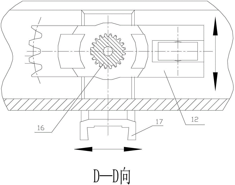
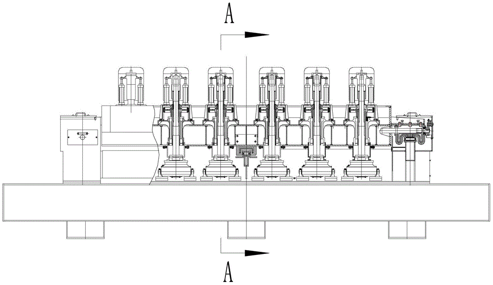
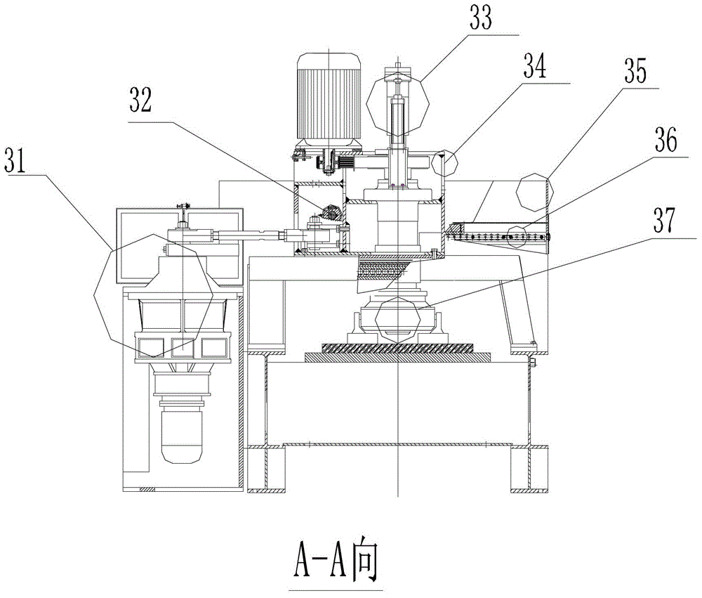
[0016] A fixed polishing machine includes a base 27 , a polishing device 21 , a support base 23 and a beam 22 . Such as Figure 2B As shown, the base 27 includes a workbench for processing materials 28 below 800 mm. The support base 23 is fixed on the front and rear sides of the base 27 . The beam 22 is located on the upper part of the base 1 and is fixed on the supporting base 23 . The polishing device 21 is fixed on the crossbeam 22. The polishing device 21 includes a grinding disc 24 with an outer diameter greater than 800mm, a motor 30 that drives the grinding disc to rotate, and an upper assembly 28 that connects the motor and the grinding disc. The grinding disc 24 also includes a processing part located at the bottom of the grinding disc—a grinding block 26, the grinding block 26 is fixed on the grinding block seat 25 through a V-shaped bayonet; On the spline shaft that can rotate on the outside.
[0017] Such as Figure 2A As shown, multiple groups of mold throwin...
PUM
| Property | Measurement | Unit |
|---|---|---|
| Outer diameter | aaaaa | aaaaa |
Abstract
Description
Claims
Application Information
 - Generate Ideas
- Intellectual Property
- Life Sciences
- Materials
- Tech Scout
- Unparalleled Data Quality
- Higher Quality Content
- 60% Fewer Hallucinations
Browse by: Latest US Patents, China's latest patents, Technical Efficacy Thesaurus, Application Domain, Technology Topic, Popular Technical Reports.
© 2025 PatSnap. All rights reserved.Legal|Privacy policy|Modern Slavery Act Transparency Statement|Sitemap|About US| Contact US: help@patsnap.com