
Puller

A technology of pulling seat and screw rod, which is applied to pulling horses. It can solve the problems of low work efficiency, heavy workload, damage to the pulled objects, etc., and achieve the effect of good versatility, small workload and high work efficiency

Active Publication Date: 2015-06-17
WUXI XUELANG ENVIRONMENTAL TECH CO LTD
View PDF7 Cites 0 Cited by
  • Summary
  • Abstract
  • Description
  • Claims
  • Application Information

AI Technical Summary

Problems solved by technology

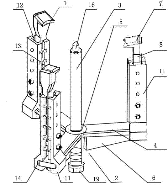
[0002] The extension range of the existing puller is determined by the diameter of the circle where the three pull feet are located, and the stretch is determined by the length of the pull feet and the screw. With the rotation of the screw, the distance between the pull feet and the surface of the pulled object The included angle will change, and it is easy to slip or the screw rod deviates from the center of the pulled object, or even damage the pulled object; and in order to ensure the stability of the puller, the extension of the puller with a certain extension range is also limited, that is, a puller Poor versatility for objects of different depths, usually requires multiple pullers to complete a type of work, low work efficiency and heavy workload

Method used


Image

  • Puller
  • Puller
  • Puller

Examples


Embodiment Construction

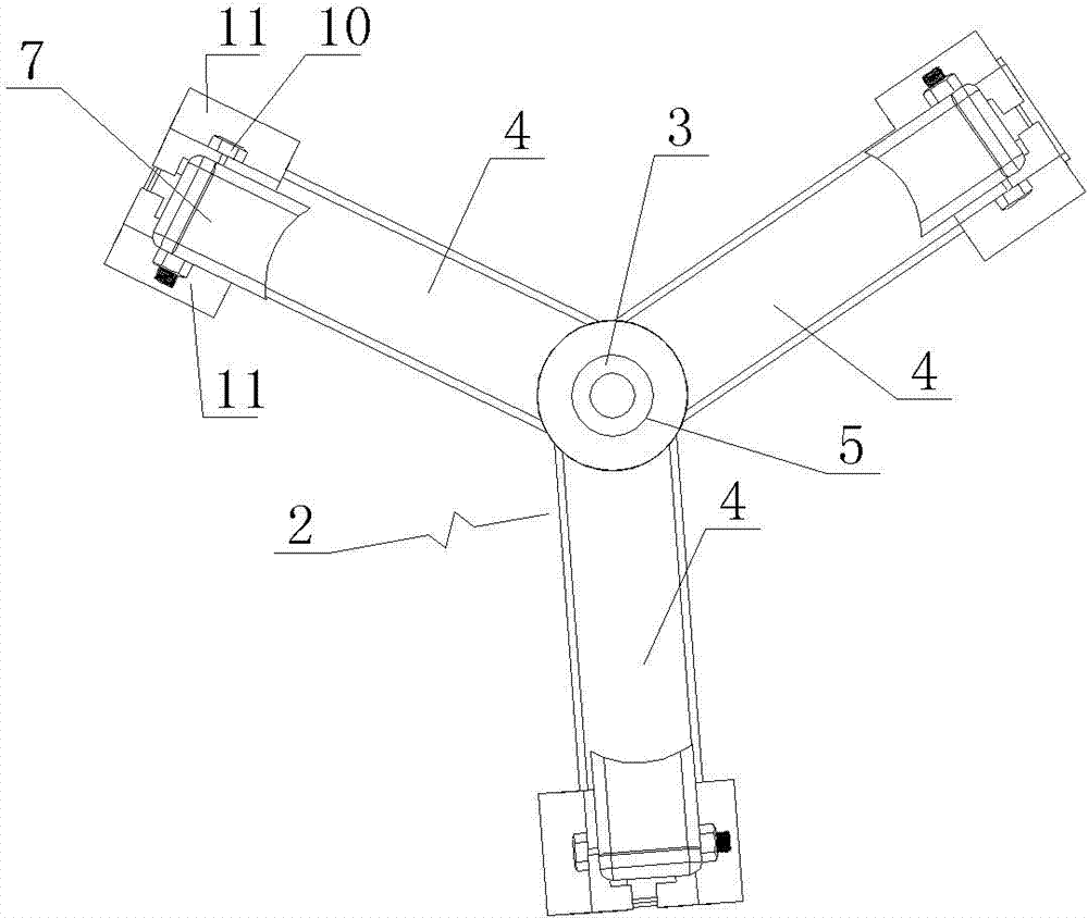
[0014] See figure 1 , figure 2 , image 3 , Figure 4 , which includes three pull feet 1, a pull seat 2, and a screw rod 3, the center of the pull seat 2 is provided with a screw rod 3, and the three pull feet 1 are evenly distributed on the pull seat 2, and the pull seat The bottom of 2 has three pedestals 4, and its center is provided with threaded hole 5, and three pedestals 4 circumferential direction are evenly distributed on the periphery of described threaded hole 5, and the bottom surface of each described pedestal 4 is provided with downward convex The positioning guide rail 6, the screw rod 3 runs through the threaded hole 5, the pull foot 1 includes the upper claw 7, the middle vertical rod 8, the bottom positioning boss 9, and the fixing bolt 10 is connected to the pair of connecting pieces 11. Form an upper vertical groove 12, a uniform longitudinal positioning groove 13, and a lower chute 14, the upper vertical groove 12 is clamped with the middle vertical ro...


PUM


Abstract

The invention provides a puller. The stretching distance and the extension distance can be separately regulated, so that pulling feet and the surface of a pulled object are kept in a vertical state all the time, and pulling stability is ensured; and the extension distance can be increased as required, so that the puller is high in generality to parts of different depths, high in working efficiency and small in working amount. The puller comprises three pulling feet, a pulling seat and a screw rod, wherein the screw rod is arranged in the center of the pulling seat; and the three pulling feet are uniformly distributed on the pulling seat. The puller is characterized in that three bases are arranged at the bottom of the pulling seat; a threaded hole is formed in the center of the pulling seat; the three bases are uniformly distributed at the periphery of the threaded hole along the circumferential direction; a downwardly-convex positioning guide rail is arranged on the bottom surface of each base; the screw rod penetrates through the threaded hole; each pulling foot comprises an upper pulling claw, a middle vertical rod and a bottom positioning boss; and a fixing bolt is connected with paired connection sheets to form an upper vertical groove, longitudinal positioning grooves which are uniformly distributed, and a lower sliding groove.

Description

technical field [0001] The invention relates to the technical field of tools for pulling and separating objects, in particular to a puller. Background technique [0002] The extension range of the existing puller is determined by the diameter of the circle where the three pull feet are located, and the stretch is determined by the length of the pull feet and the screw. With the rotation of the screw, the distance between the pull feet and the surface of the pulled object The included angle will change, and it is easy to slip or the screw rod deviates from the center of the pulled object, or even damage the pulled object; and in order to ensure the stability of the puller, the extension of the puller with a certain extension range is also limited, that is, a puller The versatility for objects of different depths is poor, usually multiple pullers are needed to complete a type of work, the work efficiency is low and the workload is heavy. Contents of the invention [000...

Claims


Application Information

Patent Timeline
Patent Type & Authority Patents(China)
IPC IPC(8): B25B27/02
Inventor 蒋洪元王飞飞
Owner WUXI XUELANG ENVIRONMENTAL TECH CO LTD
Learn More