
Elevating device special for viaduct maintenance construction
A lifting device and viaduct technology, applied in the erection/assembly of bridges, bridges, bridge maintenance, etc., can solve the problems of low efficiency, large space occupation, high cost, etc., and achieve the effect of high efficiency, simple structure, convenient and flexible construction
- Summary
- Abstract
- Description
- Claims
- Application Information
AI Technical Summary
Problems solved by technology
Method used
Image

Examples
Embodiment 1
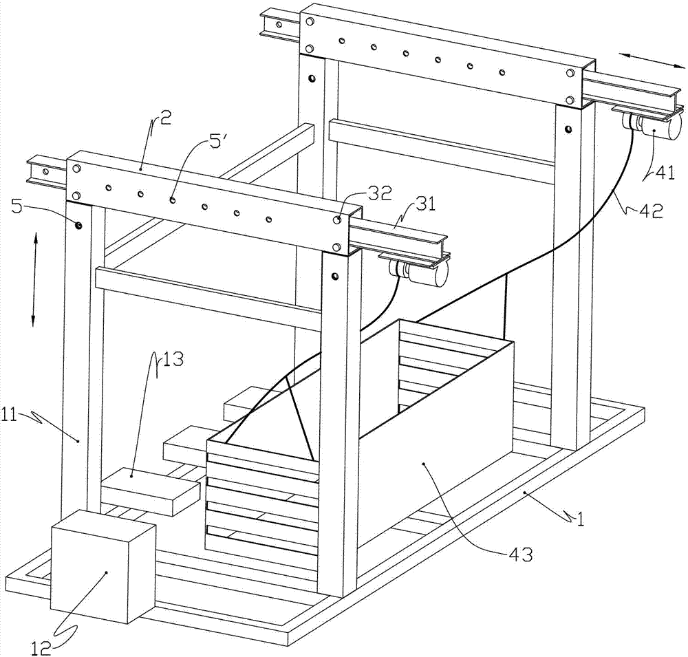
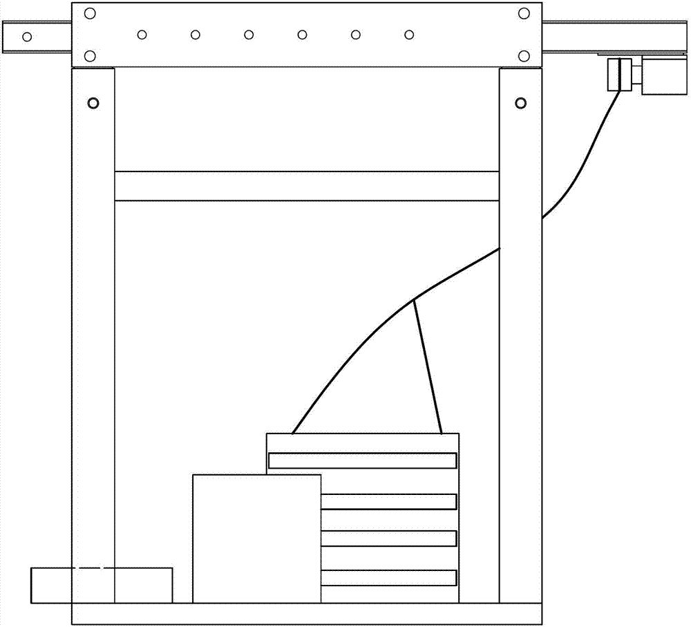
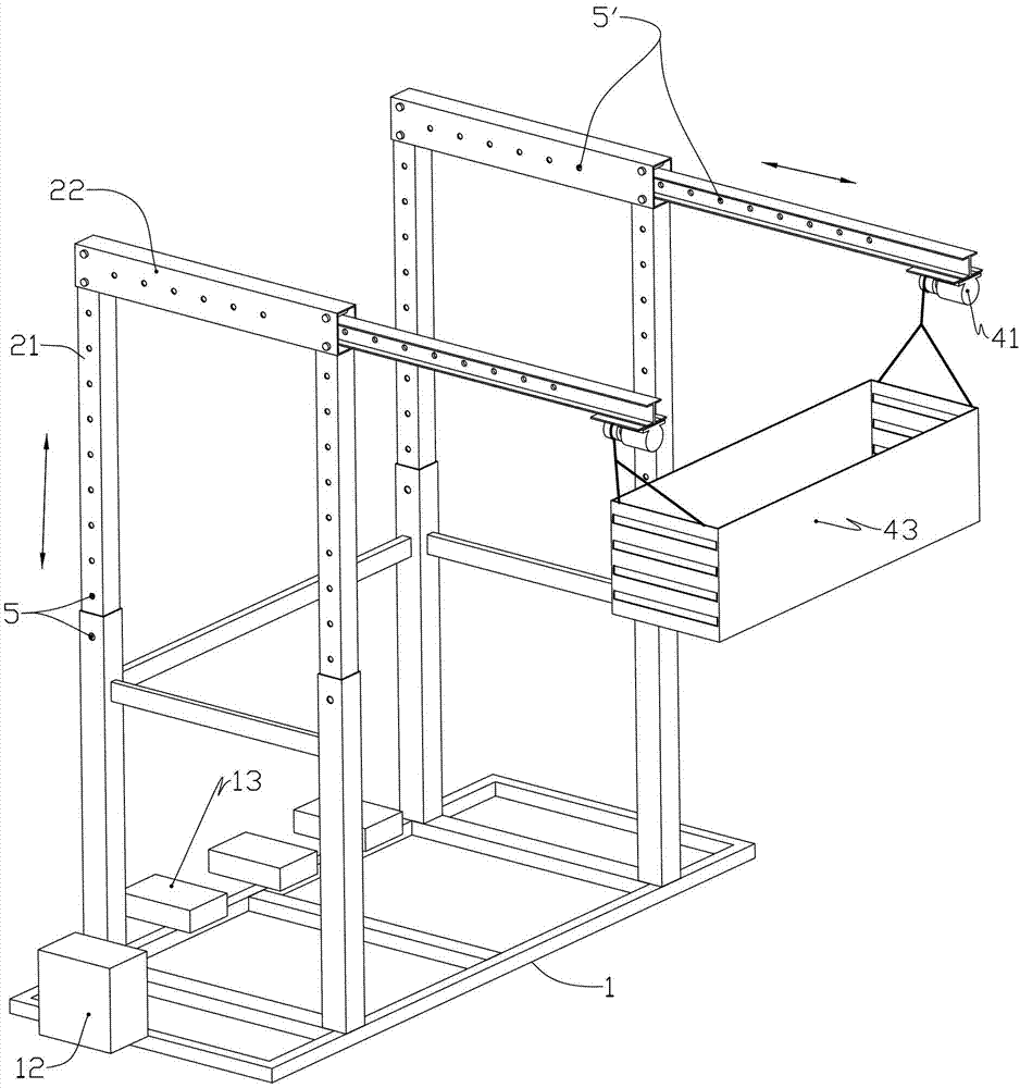
[0027] Such as Figure 1 to Figure 4 As shown, a special elevating device for viaduct maintenance and construction includes base, elevating frame, electric hoist and hanging basket, and its structure will be described in detail below.
[0028] The base 1 is a rectangular frame formed by welding steel materials such as channel steel and square steel. A pair of hollow first columns 11 are respectively welded at the front and rear ends of the base. The first column is a rectangular steel pipe. Open a circular hole 5 on the top, when making the base, the size of the base will adapt to the bucket of the vehicle that needs to be carried.
[0029] The lifting frame 2 is a "door" shape composed of two second columns 21 and a second beam 22, which is made of rectangular steel by welding, and the second column 21 is matched with the first column, and on the second column There are a plurality of round holes 5 from top to bottom, and through the round holes between the two columns with ...
Embodiment 2
[0036] The difference from the first embodiment is that the locking mechanism no longer uses simple positioning pins for locking and positioning. Such as Figure 7 , comprising a gear 61, a rack 62, a worm gear mechanism 63 and a drive end 64, the rack gear 62 is installed on the second column, the gear 61 is installed on the first column, and the gear is connected with the worm gear mechanism, and the drive end 64 is a hand wheel, the driving worm gear mechanism at the driving end acts. The same mechanism can also be applied between the first cross beam and the second cross beam in a horizontal state, and is used to drive the extension and retraction of the first cross beam. The locking purpose can be achieved by using the self-locking performance of the worm and gear mechanism, and it is convenient to use. The structure can be applied between two columns or / and between two beams.
[0037] As a modification of this embodiment, the driving end is a motor, forming an automati...
Embodiment 3
[0039] Such as Figure 8 as shown,
[0040] The difference from Embodiment 1 is that the first cylinder 91 is used to drive between the first column and the second column, that is, the two ends of the first cylinder 91 are installed on the beam between the second beam and the column through pins respectively, In this way, the telescopic movement of the two uprights can be driven by the jacking action of the first oil cylinder 91 . Similarly, a second oil cylinder 92 may also be installed between the first beam and the second beam, and the telescopic movement of the first beam in the left and right direction is driven by the second oil cylinder 92 . It is easy to understand that this structure needs to cooperate with a hydraulic station and a hydraulic control system to control its movement reasonably.
[0041] The advantage of this structure is that it can meet the functions of automatic lifting and lateral extension, similar to a hydraulic equipment, but the disadvantage is...
PUM
 Abstract
Description
Claims
Application Information