Method for calibration of optical centering device fixed to base

An optical plummet and base technology, which is applied to instruments, measuring devices, etc., can solve the problems that the plummet cannot be rotated, the centering error can be measured, and it is difficult to guarantee, so as to solve the problem of low accuracy and improve the calibration accuracy. Effect

Active Publication Date: 2013-10-02
CHINA FIRST METALLURGICAL GROUP
View PDF3 Cites 10 Cited by
  • Summary
  • Abstract
  • Description
  • Claims
  • Application Information

AI Technical Summary

Problems solved by technology

However, the optical centering device of some measuring instruments is designed on the base. The centering device cannot rotate with the collimating part during inspection, and its centering error cannot be accurately measured by conventional inspection methods. The inspection method of hanging the vertical ball on the tripod is used for detection and correction. Because the vertical ball is affected by the environment, processing accuracy, tripod and other external influences, it is difficult to guarantee the accuracy of the centering error within 1 mm.

Method used


Image

  • Method for calibration of optical centering device fixed to base
  • Method for calibration of optical centering device fixed to base

Examples


Embodiment Construction

[0016] The present invention will be further described below in conjunction with accompanying drawing.

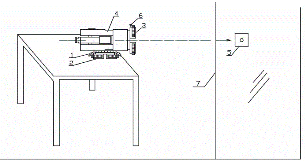
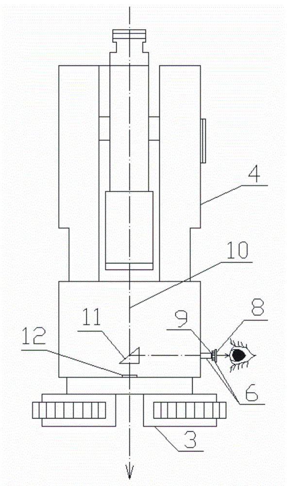
[0017] The calibration method of the optical plummet fixed on the base, the structure of the instrument to be checked is as follows figure 2 shown by figure 2 It can be seen that it includes an aiming part 4, an optical plummet 6, and a base, the aiming part 4 is movably connected to the base, and the optical plummet 6 is fixed on the base, figure 2 It is a schematic diagram of the state during the implementation of the present invention. Depend on figure 2 It can be seen that its calibration method comprises the following steps:

[0018] a. Put the spare base 2 on the edge of the table facing the wall 7, put the rag 1 on the spare base 2, and place the instrument to be tested horizontally on the spare base 2 covered with the rag Above, the function of the rag 1 is to increase the frictional force between the instrument under test and the spare base, keep the aiming...


PUM


Abstract

The invention discloses a method for calibration of an optical centering device fixed to a base. The method comprises the following steps of 1, horizontally putting an apparatus needing to be detected on a stand-by base, and keeping a state that a base of the apparatus is hung at an outer side of a table edge and faces vertically to a wall surface, 2, observing an eye lens of an optical centering device of the apparatus needing to be detected so that a wall position corresponding to a crosshair is found and pasting a crosshair scoring board to the wall position, and 3, lightly turning the base of the apparatus for 180 degrees, and observing a relative position relationship of two crosshair cross points, wherein if the reticle cross point of the apparatus is in a circle drawn on the crosshair scoring board, the apparatus is qualified and if the cross point is outside the circle, a centering error exists and a correction process must be carried out. The method is fast and convenient and greatly improves a correction precision.

Description

technical field [0001] The invention relates to a calibration method for an optical plummet fixed on a base. Background technique [0002] The centering error of the centering device is directly related to the accuracy of the measurement results. The centering device is divided into an optical centering device and a laser centering device. The optical centering device is more widely used because of its high precision. The general optical centering device The middle device is fixed on the collimating part of the instrument, figure 1 It is the detection schematic diagram of the optical plummet in the conventional vertical state, which is composed of figure 1 It can be seen that the reflected light of the object first passes through the objective lens 12 of the plummet, and then enters the human line of sight through the prism 11 of the plummet, the reticle 9 of the plummet and the eyepiece 8 of the plummet. The collimating part rotates along the vertical axis 10 of the instr...

Claims


Application Information

Patent Timeline
Patent Type & Authority Applications(China)
IPC IPC(8): G01C25/00
Inventor 桂祁东刘思农何红玲
Owner CHINA FIRST METALLURGICAL GROUP
Why Eureka
Try Eureka