Inductive current valley detection method and constant current control method for LED drive circuit

A technology of LED drive and inductor current, which is applied in the field of constant current control, can solve the problems of uncertain and inconstant average current, and the inability to accurately control the average current, etc., and achieve the effect of good constant current and precise control

Active Publication Date: 2019-02-12
UNIV OF ELECTRONICS SCI & TECH OF CHINA
View PDF6 Cites 2 Cited by
  • Summary
  • Abstract
  • Description
  • Claims
  • Application Information

AI Technical Summary

Problems solved by technology

[0007] Aiming at the problem that the above-mentioned sampling resistor between the power switch tube and the ground cannot detect the valley current of the LED constant current drive circuit of Buck topology in the traditional peak current control mode, the patent number of this invention is ZL2014102500721, and the patent name is a kind of Based on the current control method proposed by the constant current output control device of the LED drive circuit, a valley current detection method and a method for realizing constant current control using the valley current detection method proposed by the present invention are proposed, avoiding the The valley current cannot be determined and the average current is uncertain or even not constant, and the average current cannot be precisely controlled

Method used


Image

  • Inductive current valley detection method and constant current control method for LED drive circuit
  • Inductive current valley detection method and constant current control method for LED drive circuit
  • Inductive current valley detection method and constant current control method for LED drive circuit

Examples


Embodiment Construction

[0036] The technical solution of the present invention will be described in detail below in conjunction with the accompanying drawings.

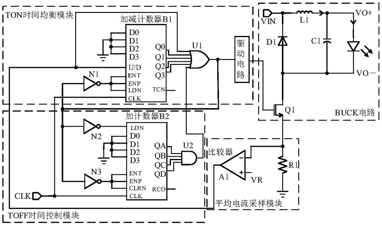
[0037] Such as image 3As shown, the applicable LED drive circuit of the present invention includes a BUCK circuit and an average current sampling module, the average current sampling module includes a sampling resistor R1 and a comparator A1, the negative input terminal of the comparator A1 is used as the input terminal of the average current sampling module and is passed through the sampling The resistor R1 is connected to the ground, and its positive input terminal is connected to the reference voltage VR; the BUCK circuit includes a switch tube Q1, an inductor L1, a diode D1, and a capacitor C1. The inductor L1 and capacitor C1 are connected in series with the diode D1 in parallel with the input voltage VIN and the switch tube Q1. Between the drains, the source of the switch tube is connected to the input terminal of the average current ...


PUM


Abstract

The invention belongs to the technical field of electronic circuitry and relates to an inductive current valley detection method and constant current control method for an LED drive circuit. The inductive current valley detection method which detects inductive current valley in n-th operating cycle of the LED drive circuit includes: using average current of inductive current via reference voltageand sample resistance of the LED drive circuit; detecting maximum values of voltage of two ends of the sample resistance in the n-th operating cycle when a switch tube is on; when current flowing through the sample resistance is equal to that flowing through an inductor, using the maximum values of voltage of the two ends of the sample resistance and the sample resistance to calculate peak value of inductive current in the n-th operating cycle; using the average current and peak current of the inductive current in the n-th operating cycle to calculate valley value of the inductive current. Theconstant current control method for the LED drive circuit sets inductive current valley of each operating cycle as peak current of the inductive current in a previous operating cycle so as to arriveat constant current control.

Description

technical field [0001] The invention belongs to the technical field of electronic circuits, and in particular relates to a method for detecting a valley value of inductance current and a constant current control method for detecting an LED drive circuit. Background technique [0002] LED has become the mainstream of today's lighting sources because of its energy saving, high reliability, long life and environmental friendliness. In the field where the LED power is less than 20W, the buck topology non-isolated structure is mainly used to drive, which not only ensures the conversion efficiency but also ensures a high cost performance. On the other hand, because of the unique current-voltage transfer characteristics of LEDs, small voltage fluctuations will produce large current fluctuations, so now a constant current method is generally used to drive LEDs to ensure that the brightness of LEDs remains stable, while usually The average value of the inductor current is used to ch...

Claims


Application Information

Patent Timeline
Patent Type & Authority Applications(China)
IPC IPC(8): H05B33/08H05B44/00
CPCH05B45/00Y02B20/30
Inventor 方健段艳秋雷一博王定良冯垚荣王卓张波
Owner UNIV OF ELECTRONICS SCI & TECH OF CHINA
Why Eureka
Try Eureka