Compact waveguide power divider

A compact, power divider technology, used in waveguide-type devices, electrical components, connecting devices, etc., can solve the problems of difficult power and phase accuracy, narrow operating bandwidth, guaranteed, etc., to achieve flexible power distribution ratio and phase accuracy. high effect

Active Publication Date: 2013-10-02
成都赛纳赛德科技有限公司
View PDF8 Cites 3 Cited by
  • Summary
  • Abstract
  • Description
  • Claims
  • Application Information

AI Technical Summary

Problems solved by technology

It is difficult to guarantee the power and phase accuracy in the broadband range when the two-way unequal division and multi-way power distribution
Another problem with the above-mentioned power splitter is that the working bandwidth is narrow, and it is difficult to cover the full bandwidth of the waveguide
When the above-m

Method used


Image

  • Compact waveguide power divider
  • Compact waveguide power divider
  • Compact waveguide power divider

Examples


Example Embodiment

[0026] Implementation example 1

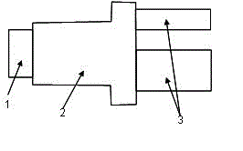
[0027] like figure 2 shown.

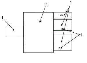
[0028] A compact waveguide power splitter, comprising an input end 1, a transition section 2, and at least two output ends 3, the input end 1 is located at the left end of the transition section 2, all output ends 3 are located at the right end of the transition section 2, the input end 1 and the output end 3 are connected with the transition section 2.

[0029] The shape of any cross section of the transition section 2 perpendicular to its centerline or axis from left to right is rectangular.

[0030] The shape of the interface between the input end 1 and the output end 3 at the place connected to the transition section 2 is a rectangle whose height of the transition section 2 is less than 2 / 3 of the depth of the transition section 2, and the output end 3 is at the transition section 2. The right side is arranged in the order of first, second...last from top to bottom, the upper edge of the right end of the...

Example Embodiment

[0045] Implementation Example 2

[0046] like Image 6 . The main difference from the implementation example 1 is that the power splitter is a three-way power splitter. The number of the output ends 3 is 3 or more than 3, each of the output ends 3 is provided with a waveguide discontinuity structure, the waveguide discontinuity structure is a waveguide step, a tuning screw, or can cause a reflection coefficient on the waveguide For other protrusions or depressions greater than or equal to -30dB and less than or equal to -15dB, the electrical length between the center of the waveguide discontinuity structure and the right end face of the transition section 2 is greater than 30 degrees or equal to and less than or equal to 60 degrees. The first and third outlets 3 are bent away from the other outlets 3 .

[0047] The above are examples only. In actual production, the number of output terminals can be 2, 3, 4, up to 10 or more.


PUM


Abstract

The invention discloses a compact waveguide power divider which comprises an input end 1, a transitional section 2, and at least two input ends 3. By controlling the width of the output end 3 and the thickness of a wall between each two adjacent output ends 3, and enabling the width and the thickness to be satisfied with a certain proportional relation, the input power can be well distributed into two ways to ten ways according to arbitrary power distribution ratio in waveguide full bandwidth. The compact waveguide power divider can be widely applied to military and civil fields of antenna array, phased array radar and power synthesis, missile guidance, communication and the like.

Description

technical field [0001] The invention relates to a power divider. Specifically, it relates to a two-way or multi-way equal or unequal compact waveguide power divider with high accuracy in amplitude and phase within a broadband range. Background technique [0002] The power splitter is a common component in modern microwave communication and military electronic systems. Due to its high power capacity and low insertion loss, waveguide power splitters are widely used. The waveguide power divider can be used alone, or can be connected in series to form a multi-channel power divider network, which is used in the fields of phased array radar, antenna array and power combination. Existing waveguide power splitters mainly include E-plane T-branches, H-plane T-branches, waveguide magic T, H-plane waveguide crack bridges, etc. Among them, the first two devices can realize very good two-way equal division. It is difficult to guarantee the power and phase accuracy in the broadband ra...

Claims


Application Information

Patent Timeline
IPC IPC(8): H01P5/16H01P5/20
Inventor 王清源谭宜成赵柯
Owner 成都赛纳赛德科技有限公司
Why Eureka
Try Eureka