Zero-crossing detection circuit

A zero-crossing detection circuit and detection unit technology, applied in the direction of measuring electrical variables, measuring current/voltage, measuring devices, etc., can solve problems such as multi-power consumption, difficulty in detection accuracy, signal attenuation, etc., and achieve strong anti-interference ability , fast convergence speed, reduce the effect of the device

Active Publication Date: 2017-02-15
HI TREND TECH SHANGHAI
View PDF8 Cites 2 Cited by
  • Summary
  • Abstract
  • Description
  • Claims
  • Application Information

AI Technical Summary

Problems solved by technology

[0005] like figure 1 as shown, figure 1 in the zero-crossing detection circuit, although the figure 1 Fewer electronic devices are used in the system, but the load of the peripheral circuit will increase more power consumption and waste electric energy
At the same time, the disadvantage of optocoupler 2 is that the signal will be seriously attenuated and distorted, which is more difficult for the accuracy of detection.
[0006] like figure 2 shown, although figure 2 reduces load power dissipation, but figure 2 However, more electronic devices are added to the zero-crossing detection circuit, which will increase the cost of detection, and the structure is complicated and not easy to maintain and protect.
At the same time, the defects of the optocoupler 2 cannot be avoided, and neither the existing technology nor the combination of the two existing technologies can achieve a better detection effect.

Method used


Image

  • Zero-crossing detection circuit
  • Zero-crossing detection circuit
  • Zero-crossing detection circuit

Examples


Embodiment 1

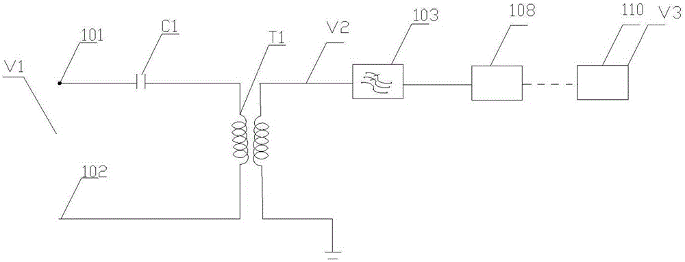
[0043] as attached image 3 As shown, a zero-crossing detection circuit described in this embodiment includes: a coupling unit, the coupling unit has a first input terminal 101 and a second input terminal 102, and the coupling unit is used to convert the input signal V1 of the first and second input terminals Output after coupling.

[0044] The filtering unit 103 is connected with the coupling unit to receive the input signal output by the coupling unit, and perform filtering processing on the input signal to form a filtered signal output. The first input terminal 101 is connected to one end of the primary winding of a transformer T1 through a capacitor C1, also That is, the capacitor C1 is connected between the one end of the primary winding of the transformer T1 and the first input end 101 , while the second input end 102 is connected to the opposite end of the primary winding of the transformer T1 . One end of the secondary winding of the transformer T1 is connected to the...

Embodiment 2

[0060] This embodiment is a model circuit circuit based on the circuit of Embodiment 1, as attached Figure 4 As shown, the coupling unit of the present invention has a first input terminal 101 and a second input terminal 102; the first input terminal 101 is connected to the capacitor C1, and there is a coupling between the second input terminal 102 and the output terminal of the capacitor C1. Effective inductance L1, the equivalent inductance L1 is the equivalent inductance of the transformer T1 in the first embodiment, and one end of the equivalent inductance L1 corresponding to the first input end 101 is connected to the input end of the filter unit 103, and the output end of the filter unit 103 is connected to, etc. The effective resistance R1, the equivalent resistance R1 is figure 1 The equivalent resistance of the analog-to-digital conversion unit 108 .

[0061] In a preferred embodiment of this embodiment, the opposite end of the second input end 102 and the equivalen...

Embodiment 3

[0065] This embodiment is based on the actual circuits of Embodiments 1 and 2, as attached Figure 5 As shown, the coupling unit in this embodiment has a first input terminal 101 and a second input terminal 102; the first input terminal 101 is connected to one end of the primary winding of a transformer T1 through a capacitor C1, that is, the capacitor C1 is connected to the transformer T1 Between this end of the primary winding and the first input end 101, while the second input end 102 is connected to the opposite end of the primary winding of the transformer T1; both ends of the secondary winding of the transformer T1 are connected to the LPF module 109 for enhanced detection Accuracy, discharge interference error. LPF module 109 with figure 1 and figure 2 The filter unit 103 in has the same function, where the LPF module 109 filters out the high-frequency noise of the power line.

[0066] A preferred embodiment of the present invention: For example, between the first i...


PUM


Abstract

The invention relates to the field of semiconductors, and more particularly to a zero-crossing detection circuit. The zero-crossing detection circuit has a coupling unit having a first input terminal and a second input terminal and used for coupling and outputting an input signal between the first input terminal and the second input terminal; a filter unit connected to the coupling unit and used for receiving the input signal outputted from the coupling unit and filtering the input signal to form a filter signal output; a detection unit connected with the filter unit and used for receiving the filter signal and computing the filter signal according to a predetermined computing method to form detection phase information. The detection phase information V3 acquires the phase information V2 of the signal of the input terminal of the filter unit, and the phase information of the input signal V1 of the first and second input terminals is calculated by the phase information V2 of the signal of the input terminal of the filter unit, and whether zero crossing occurs is determined by determining the phase information of the input signal V1 at the first and second input terminals. The zero-crossing detection circuit makes a zero crossing signal have high precision, and is low in power consumption and fast in convergence speed.

Description

technical field [0001] The invention relates to the field of semiconductors, in particular to a zero-crossing detection circuit. Background technique [0002] Zero-crossing information is very important in the field of power carrier. It can confirm the phase through zero-crossing information and clarify the topological relationship of the entire station area. [0003] At present, power companies need to provide zero-crossing information, and power line carrier zero-crossing detection is currently realized through optocoupler circuits, but the optocoupler circuit makes the accuracy of zero-crossing signals relatively poor, and the jitter of zero-crossing signals is relatively severe. The load will also increase the power consumption. If the jitter of the zero-crossing signal and the power consumption of the load are reduced, too many electronic devices are required, thereby increasing the detection cost. At the same time, after the AC signal passes through the carrier optoc...

Claims


Application Information

Patent Timeline
Patent Type & Authority Applications(China)
IPC IPC(8): G01R19/175
Inventor 何巍张旭明潘宇
Owner HI TREND TECH SHANGHAI
Why Eureka
Try Eureka