

DC low-voltage double-push-injection phase-lock power synthesis metal halide lamp
An injection phase-locked, low-voltage technology, used in electric light sources, electrical components, lighting devices, etc., can solve problems such as power imbalance, oscillating voltage phase inconsistency, etc., to stabilize lighting, prolong service life, and avoid device temperature rise The effect of power imbalance due to changes in oscillation frequency
Inactive Publication Date: 2013-10-02
张妙娟
View PDF4 Cites 0 Cited by
- Summary
- Abstract
- Description
- Claims
- Application Information
AI Technical Summary
Problems solved by technology
However, the phase of the power synthesis oscillation voltage is inconsistent, and the nonlinear intermodulation affects the power imbalance
Method used
View moreImage
Smart ImageViewing Examples

Examples
Embodiment
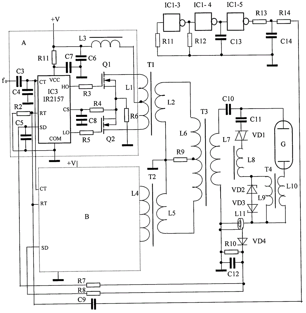
[0022] Embodiment The direct current low voltage is 30V, the inverter current is 2.7A, and the output power of double-push is synthesized to match a 70W metal halide lamp, the efficiency is 86%, the light efficiency is high, the light is stable, and the service life is long.
Login to View More PUM
 Abstract
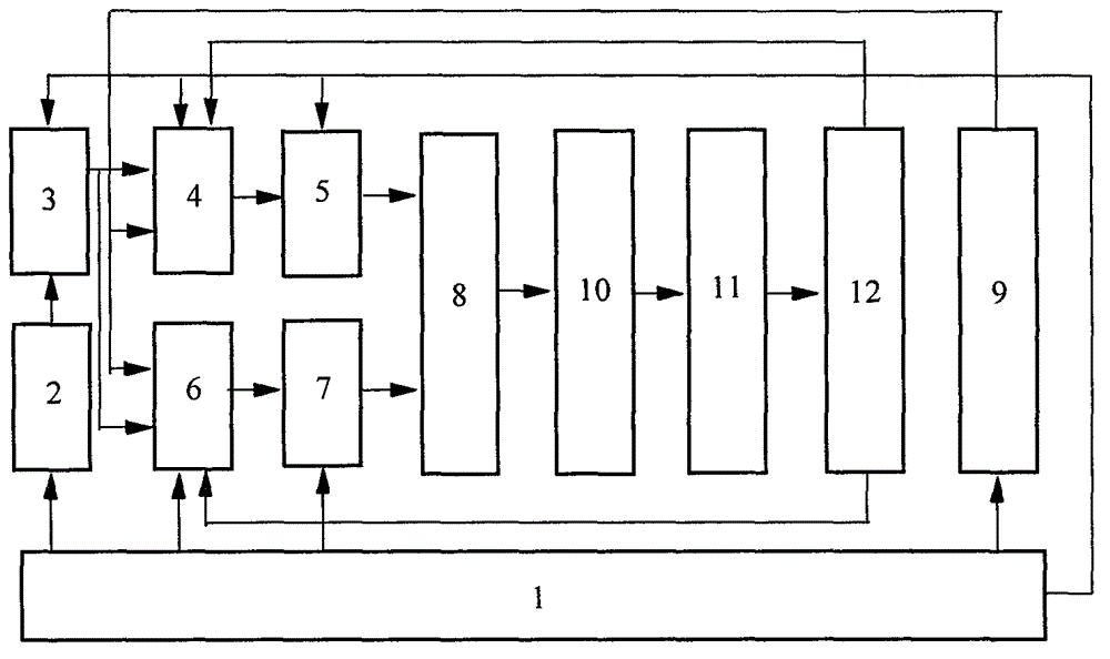
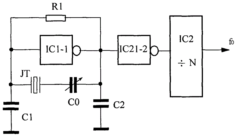
The invention relates to the electric light source lighting technology field, in particular to a DC low-voltage double-push-injection phase lock power synthesis metal halide lamp. The RC oscillators of two self-oscillating chips 4, 6 are jointly connected with a capacitor C4 and a resistor R2 to carry out synchronous oscillation. The self-oscillating chip 4 and a push-pull amplifier A output a power transformer T1; the self-oscillating chip 6 and a push-pull amplifier B output a power transformer T2; the power transformer T1 and the power transformer T2 are fed into an addition coupler in an anti-phase manner; the power synthesis is realized and the voltage is increased, and the lamp is turned on; a reference crystal oscillator signal is injected into an RC oscillator phase lock of the two self-oscillating chips 4,6 through a frequency divider; the oscillation frequency change, power imbalance and lighting decreasing because the device temperature is too high are prevented; a frequency modulated signal generator outputs a triangular wave low frequency signal which is connected with the RC oscillators of the two self-oscillating chips 4,6 so as to prevent the lamp from flashing. The metal halide lamp of the invention is suitable for the lighting conditions of DC low-voltage and large current power supply metal halide lamps.
Description
technical field [0001] The invention relates to the technical field of electric light source lighting, in particular to a DC low-voltage double-push injection phase-locked power synthesis metal halide lamp. Background technique [0002] In the prior art, electronic ballasts generally use LC or RC oscillators as metal halide lamp light sources, and the oscillation frequency generated is affected by poor stability of temperature changes, and the power is unstable and the light intensity drops. Although the structure is simple and the cost is low. Due to the low power supply voltage, it is necessary to increase the device current to obtain high-power lighting, so that the power consumption of the oscillating power tube will increase sharply and the temperature will rise too high, resulting in a change in the oscillation frequency. As a result, the power amplitude of the light will be unbalanced as the frequency changes. At the same time, when the large current passes through th...
Claims
Login to View More Application Information
Patent Timeline
 Patent Type & Authority Applications(China)
IPC IPC(8): H05B41/285
CPCY02B20/00
Inventor 阮树成张妙娟
Owner 张妙娟