Rotary clamping mechanism and application method thereof

A technology of clamping mechanism and connecting parts, which is applied in the direction of decorative art, artist hand tools, etc., can solve the problems of blade storage and the inconvenience of removing the blade of the carving knife, and achieve the effect of convenient operation

Inactive Publication Date: 2013-10-09
SHANGHAI QIMAI HARDWARE
View PDF4 Cites 8 Cited by
  • Summary
  • Abstract
  • Description
  • Claims
  • Application Information

AI Technical Summary

Problems solved by technology

[0003] The invention discloses a rotary clamping mechanism and its application method, which are used to solve the pr

Method used


Image

  • Rotary clamping mechanism and application method thereof
  • Rotary clamping mechanism and application method thereof
  • Rotary clamping mechanism and application method thereof

Examples


Embodiment Construction

[0030] In order to make the technical means, creative features, objectives and effects of the invention easy to understand, the present invention will be further elaborated below in conjunction with specific diagrams.

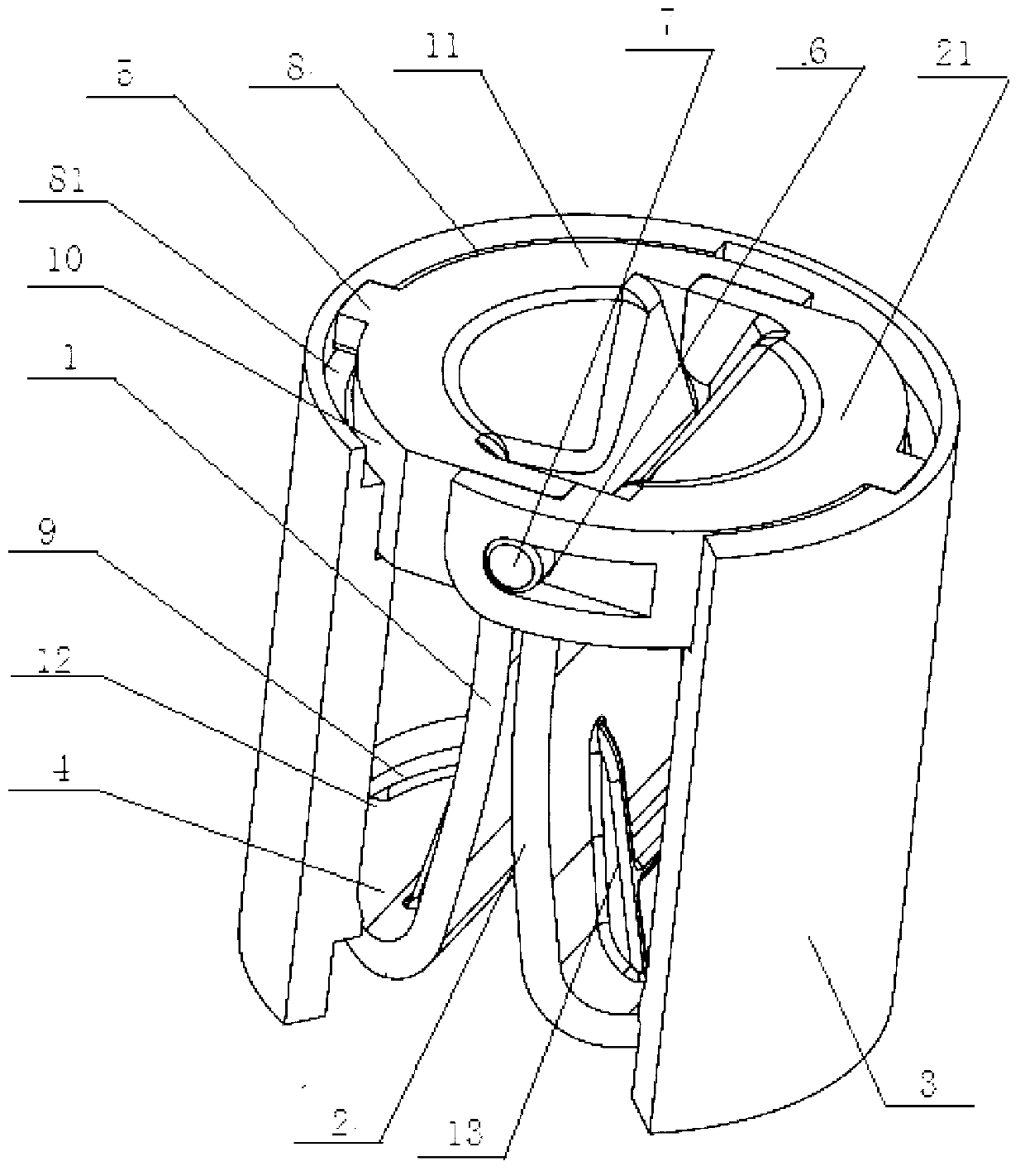
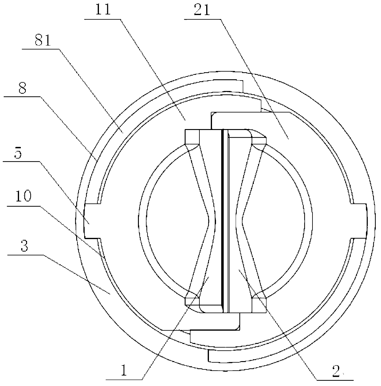
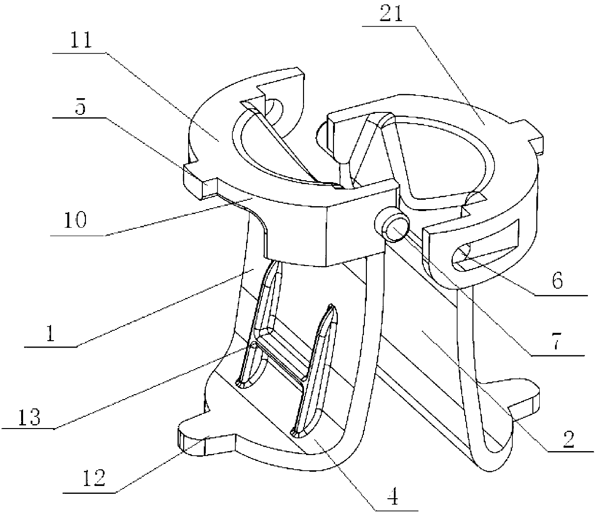
[0031] Figure 1-3 As shown, a rotary clamping mechanism, which includes: a first plate body 1, a second plate body 2, a first connecting piece 11, a second connecting piece 21 and a sleeve 3, the first connecting piece 11 is arranged on the second One end of a plate body 1, the second connecting piece 21 is arranged at one end of the second plate body 2, the first connecting piece 11 is connected with the second connecting piece 21, the first plate body 1, the second plate body 2, the first connecting piece Part 11 and the second connecting part 21 are both arranged in the sleeve 3; the first plate body 1 is reversely bent to the second plate body 2 to form an arc shape, further after the first connecting part 11 and the second connecting part 21 are connected...


PUM


Abstract

The invention discloses a rotary clamping mechanism. The rotary clamping mechanism is characterized in that a first plate body, a second plate body, a first connecting piece and a second connecting piece are all arranged inside a sleeve; the end, far away from the first connecting piece, of the first plate body is provided with an extension body along a bent face of the first plate body in an outward extending mode; the first connecting piece is in the shape of a semi-round disk, an embedding hole and an embedding piece are respectively arranged on the outer lateral faces of the arc-shaped faces at the two ends the first connecting piece; the shape of the first connecting piece is the same as the shape of the second connecting piece, the shape of the first plate body is the same as the shape of the second plate body, and the first connecting piece and the second connecting piece are matched with each other; two arc-shaped blocks are arranged on the lower edge of the inner wall of the sleeve. By the adoption of the technical scheme, the rotary clamping mechanism and an application method of the rotary clamping mechanism have the following advantages that blades can be pulled out from a cutter rod conveniently, hand sweat cannot be contacted with the blades directly, the blades can be prevented from rusting, and fingers are protected from being scratched.

Description

technical field [0001] The present invention relates to a tool clamping device, in particular to a rotary clamping mechanism and a use method thereof. Background technique [0002] As we all know, the blade of the engraving blade is inserted into the knife shaft. When not in use, the blade needs to be removed and stored to protect the blade. However, when removing the blade, people directly touch the blade surface with their fingers to complete it. , it is easy to make the sweat on the fingers contact the knife surface and cause the blade to rust. At the same time, there is a danger of being scratched, and it will also damage the gloves in the case of wearing gloves. More importantly, not everyone has the blade The force to pull out from the shank. Due to the above reasons, carving knives run into different difficulties when taking off the blade. And usually people need two hands to complete in the process of placing and sometimes seem inconvenient. Contents of the inven...

Claims


Application Information

Patent Timeline
IPC IPC(8): B44B11/00
Inventor 孙时雨
Owner SHANGHAI QIMAI HARDWARE
Why Eureka
Try Eureka