Magnetic fluid dynamic seal structure suitable for high speed

A magnetic fluid dynamic sealing, high-speed technology, applied in the direction of engine sealing, engine components, mechanical equipment, etc., to achieve good heat dissipation performance, good sealing effect, and good dynamic sealing effect.

Inactive Publication Date: 2015-09-16
南京旋妙机械设备有限公司
View PDF6 Cites 2 Cited by
  • Summary
  • Abstract
  • Description
  • Claims
  • Application Information

AI Technical Summary

Problems solved by technology

[0006] Aiming at the problem that the existing magnetic fluid dynamic sealing structure cannot overcome the centrifugal force of the magnetic fluid itself and thus cannot withstand high rotational speed, the present invention provides a magnetic fluid dynamic sealing structure suitable for high rotational speed, which has good sealing effect and good heat dissipation performance. Advantages, able to withstand the sealing surface line speed greater than 20 m / s

Method used


Image

  • Magnetic fluid dynamic seal structure suitable for high speed
  • Magnetic fluid dynamic seal structure suitable for high speed
  • Magnetic fluid dynamic seal structure suitable for high speed

Examples


Embodiment 1

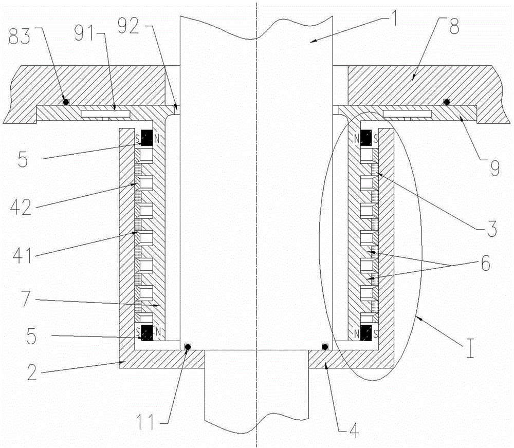
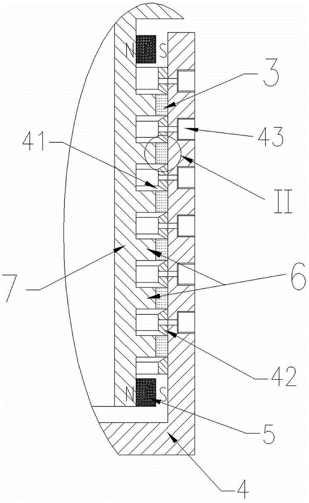
[0029] Example 1, A ferrohydrodynamic seal structure suitable for high speed, such as figure 1 , figure 2 and image 3 shown. Installed on the casing (8), it includes a cylindrical stationary magnetic pole 7 and a cylindrical rotating magnetic pole 4 coaxially sleeved outside the stationary magnetic pole 7. The stationary magnetic pole 7 is formed by a radial ring at its end. 9 is fixed with casing 8. Specifically, the stationary magnetic pole 7 is rigidly connected to the casing 8 by a radial ring 9 arranged at its end, the radial ring 9 is fixedly mounted on the casing 8 and sealed with a sealing ring 83, and the rotating magnetic pole 4 is installed in a non-vacuum environment , the radial ring 9 of the stationary pole 7 is provided with a cooling medium circulation channel 91 .

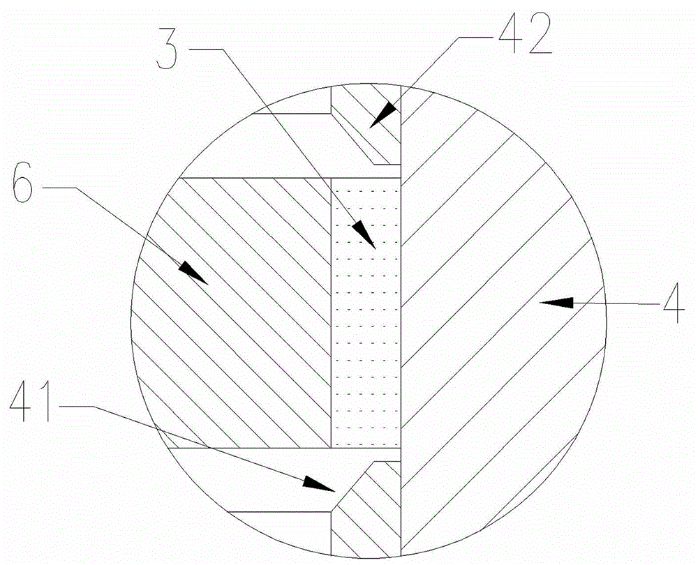
[0030] The outer surface of the cylinder of the stationary magnetic pole 7 is provided with more than two protruding cylindrical sealing rings 6, and the number of cylindrical sealing ring...

Embodiment 2

[0081] Example 2, Same as Embodiment 1, the difference is that: the inner hole of the casing 8 is provided with an annular casing protection ring 82 for limiting the radial runout range of the rotating shaft 1, and the casing 8 is provided with a cooling medium circulation Channel 81.

[0082] Such as Figure 7 As shown, the protection ring 82 is used to prevent the rotating shaft 1 from causing the rotating magnetic pole 4 to rub against the sealing ring 6 on the stationary magnetic pole 7 when the radial runout of the rotating shaft 1 is large, thereby damaging the magnetic fluid sealing structure.

Embodiment 3

[0083] Example 3, The rotating magnetic pole 4 is installed in a vacuum to meet the needs of special working conditions. Such as Figure 8 As shown, the rotating magnetic pole 4 is placed in a vacuum environment enclosed by a flange and a casing 8 .


PUM


Abstract

A magnetofluid motive sealing structure suitable for high rotation speed mainly solves the technical problem that an existing magnetofluid motive sealing structure cannot bear the high rotation speed because the existing magnetofluid motive sealing structure cannot overcome the centrifugal force of magnetofluid. The magnetofluid motive sealing structure suitable for the high rotation speed comprises a cylindrical static magnetic pole (7) and a cylindrical rotation magnetic pole (4) which is sleeved outside the static magnetic pole (7) coaxially. One end of the static magnetic pole (7) is fixed on a machine shell (8), and more than two protruding sealing rings (6) are arranged on the outer surface of a cylinder of the static magnetic pole (7). A rotating shaft (1) penetrates through an axis hole of the static magnetic pole (7) and is fixedly connected with the rotation magnetic pole (4) into a whole. The magnetofluid (3) is arranged in a radial clearance between the sealing rings (6) and the magnetic inner surface of the rotation magnetic pole (4), so that the static magnetic pole (7) is in magnetofluid motive sealing fit with the rotation magnetic pole (4). The magnetofluid motive sealing structure suitable for the high rotation speed has the advantages of being good in sealing effect and heat dissipation performance, and the linear velocity of more than 20meter per second can be borne.

Description

technical field [0001] The invention relates to a magnetic fluid dynamic sealing structure, in particular to a magnetic fluid dynamic sealing structure aimed at high rotating speed. Background technique [0002] Ferromagnetic fluid is a colloidal system formed by uniformly dispersing ferromagnetic particles in a carrier liquid. It has both strong magnetism and fluidity, and can maintain long-term stability under the action of gravity, magnetic force and other forces without producing Sedimentation and stratification. The principle of ferrofluid sealing is to use magnetic field to confine ferrofluid so that it fills the sealing space to form a "liquid O-ring", and a suitable carrier liquid can infiltrate the sealing surface well to achieve a very good sealing effect. When the saturated vapor pressure of the carrier liquid is low enough, it is difficult to volatilize even in a high vacuum environment, and the above magnetic fluid seal can be applied to vacuum sealing. The ma...

Claims


Application Information

Patent Timeline
Patent Type & Authority Patents(China)
IPC IPC(8): F16J15/42F16J15/53
Inventor 史银娥
Owner 南京旋妙机械设备有限公司
Why Eureka
Try Eureka