
FPGA-based irig-b code encoding and decoding system and its encoding and decoding method

A decoding system and encoding technology, applied in the application of multi-bit parity error detection coding, error correction/detection using block codes, data representation error detection/correction, etc., can solve the problem that the accuracy of decoding functions cannot be solved get test etc.

Active Publication Date: 2016-12-28
HARBIN INST OF TECH
View PDF4 Cites 0 Cited by
  • Summary
  • Abstract
  • Description
  • Claims
  • Application Information

AI Technical Summary

Problems solved by technology

[0003] In order to solve the problem that the existing IRIG-B code processing system needs an external IRIG-B code signal source to complete the self-inspection of the decoding system, and the accuracy of the decoding function cannot be checked, the present invention proposes an FPGA-based IRIG-B code encoding and decoding system and its encoding and decoding method

Method used


Image

  • FPGA-based irig-b code encoding and decoding system and its encoding and decoding method
  • FPGA-based irig-b code encoding and decoding system and its encoding and decoding method
  • FPGA-based irig-b code encoding and decoding system and its encoding and decoding method

Examples


specific Embodiment approach 1

[0040] Specific implementation mode 1: see figure 1 This embodiment is described. The FPGA-based IRIG-B code encoding and decoding system described in this embodiment includes a GPS / Beidou dual system module 1, an FPGA2, a single-chip microcomputer 3, a DAC chip 4, a comparator chip 5, and a host computer 6. and PCI riser card 7,

[0041] FPGA2 embedded storage control module 2-1, AC code coding control logic module 2-2, DC code coding control logic module 2-3, DC decoding control logic module 2-4 and AC code decoding control logic module 2-5 ,

[0042] The GPS / Beidou dual system module 1 is used to output time information and send it to the single-chip microcomputer 3 and the storage control module 2-1 at the same time,

[0043] The storage control module 2-1 is used to use the received time information as the original time source, and is also used to input the original time source to the host computer 6 through the PCI adapter card 7,

[0044] The single-chip microcompute...

specific Embodiment approach 2

[0053] Embodiment 2: This embodiment is a further limitation of Embodiment 1. The DAC chip 4 is implemented by a DAC7714, and the DAC7714 is a 12-bit serial input D / A converter.

specific Embodiment approach 3

[0054] Embodiment 3: This embodiment is a further limitation of Embodiment 1, and the comparator chip 5 is a zero-crossing comparator chip.


PUM


Abstract

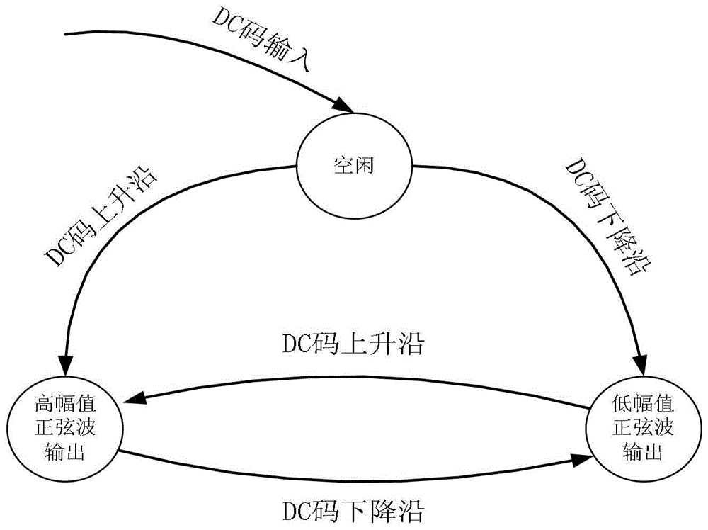
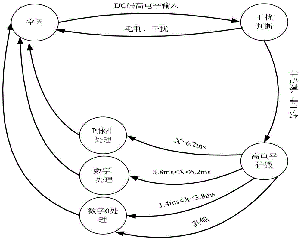
The invention discloses an IRIG-B (Inter Range Instrumentation Group) encoding and decoding system and method based on an FPGA (Field Programmable Gate Array), belonging to the technical field of communication. The system and the method solve the problems that a conventional IRIG-B code processing system needs an external signal source of IRIG-B codes to accomplish self-inspection on a decoding system, and that the accuracy of a decoding function cannot be verified. The IRIG-B encoding and decoding system based on the FPGA comprises a GPS (Global Positioning System) / beidou double-system module, the FPGA, a singlechip, a DAC (Digital-to-Analog Converter) chip, a comparer chip, a host computer and a PCI (Peripheral Component Interconnect) adapting card, wherein the GPS / beidou double-system module, the FPGA, the singlechip, the DAC chip and the comparer are integrated on a board card, and the board card is connected with the host computer through the PCI adapting card. The method comprises the following steps that: the singlechip decodes received time information and subsequently inputs the received time information into a DC (Direct Current) encoding control logic module and an AC (Alternative Current) encoding control logic module of the FPGA so as to encode a DC code and an AC code; after the encoding is accomplished, the DC code and the AC code are respectively input into the FPGA through an external loopback and are subsequently decoded; the decoding result is uploaded to the host computer. The technical scheme provided by the invention is applicable to IRIG-B encoding and decoding systems.

Description

technical field [0001] The invention belongs to the field of communication technology. Background technique [0002] With the rapid development of today's electronic technology, time synchronization has become an increasingly important application. As a serial time code, IRIG-B code is an important time synchronization transmission method. With its outstanding performance, it has become the preferred standard code type for time system equipment, and is widely used in telecommunications, electric power, military and other important industries or sectors. There are generally three ways to encode and decode IRIG-B codes: FPGA-based encoding and decoding, single-chip-based encoding and decoding, and dedicated decoding chips. However, the existing IRIG-B code processing systems are mostly aimed at the decoding of IRIG-B codes (DC codes), and an external IRIG-B code signal source is required to complete the self-check of the decoding system. It is very inconvenient in the proce...

Claims


Application Information

Patent Timeline
Patent Type & Authority Patents(China)
IPC IPC(8): H03M13/11
Inventor 王少军刘连胜周建宝庄波海彭喜元
Owner HARBIN INST OF TECH
Learn More