
Method of pressing steel ladder steps by rolling machine

A plate rolling machine and steel ladder technology, applied in the field of plate rolling, can solve the problems of high labor intensity, inconsistent overall bending style, and low production efficiency, so as to reduce production costs, improve process quality, and shorten pressing time Effect

Inactive Publication Date: 2015-10-28
SICHUAN NO 3 ELECTRIC POWER CONSTR
View PDF6 Cites 0 Cited by
  • Summary
  • Abstract
  • Description
  • Claims
  • Application Information

AI Technical Summary

Problems solved by technology

However, these methods have great deficiencies in terms of quality and benefit: the use of flower cutting bending, because only part of the cutting is used, resulting in no arc at right angles after the cutting part is bent, the overall bending style is not uniform, and the quality and craftsmanship are poor ;Using combined welding of steel plates, the entire step right angle has no arc after forming, and there are many edges and corners, so the quality of the steel ladder steps produced is defective; and the method of using lever knuckles or jack pressing, although generally can achieve the quality of the steel ladder steps. Requirements, but it requires a lot of manpower and labor intensity, resulting in low production efficiency

Method used


Image

  • Method of pressing steel ladder steps by rolling machine
  • Method of pressing steel ladder steps by rolling machine
  • Method of pressing steel ladder steps by rolling machine

Examples


Embodiment

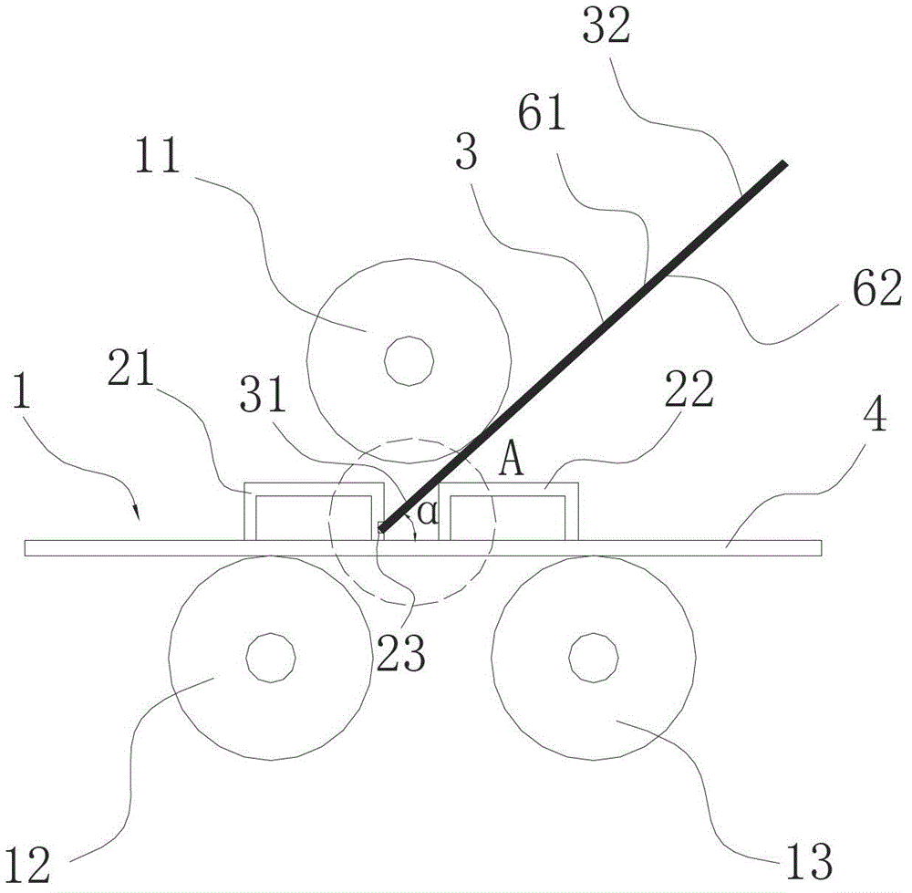
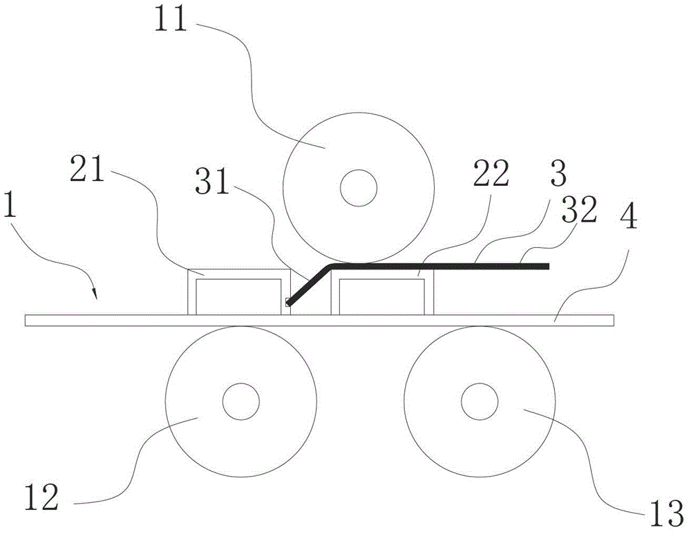
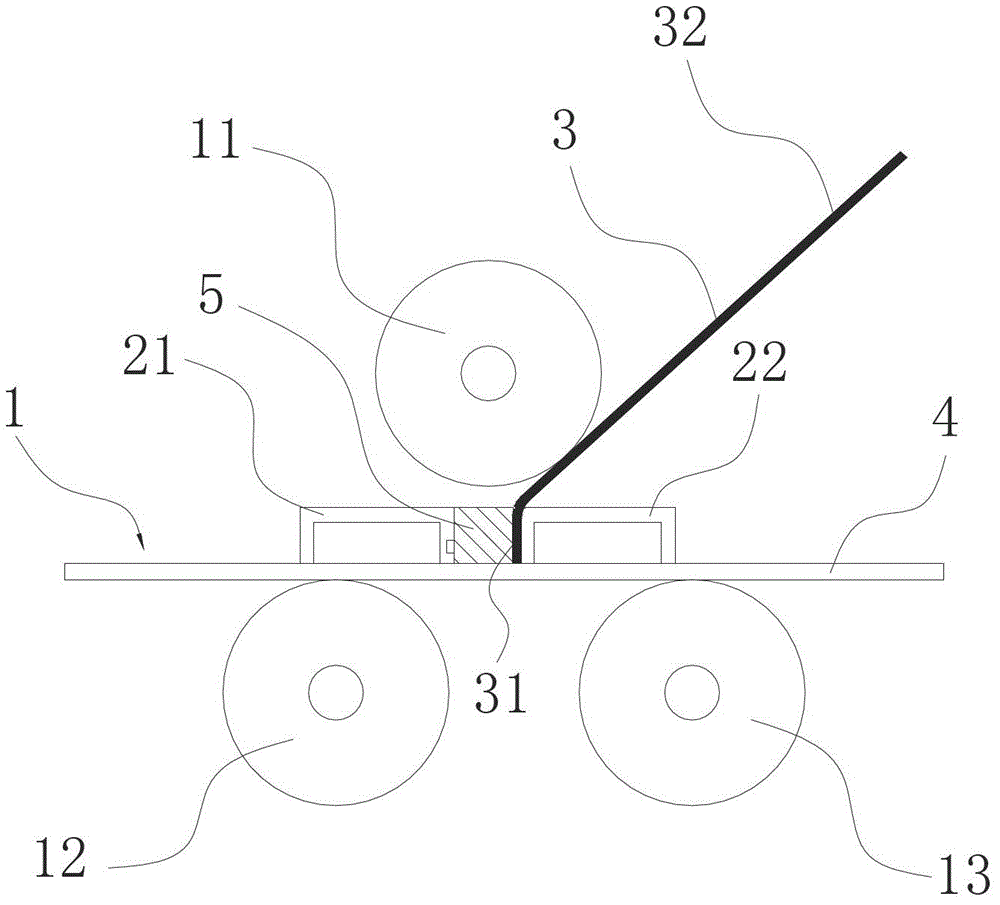
[0041] Bend the material plate 3 according to the following steps to obtain an "N"-shaped steel ladder step, and the material plate 3 adopts a patterned steel plate.

[0042] A. Two fixing plates and a backing plate 4 are made. The fixing plates include a first fixing plate 21 and a second fixing plate 22 . The first fixing plate 21 and the second fixing plate 22 have the same height h of the fixing plate, and both use channel steel.

[0043] B. Fix the first fixing plate 21 and the second fixing plate 22 on the backing plate 4, and there is a gap between the first fixing plate 21 and the second fixing plate 22; the first fixing plate 21 and the second fixing plate 22 The two fixing plates 22 have the same length L3 of the fixing plate, the material plate 3 is installed in the gap between the first fixing plate 21 and the second fixing plate 22, and the material plate 3 has a length L3≤fixing plate Length L2, one end of the material plate 3 in the gap is the folded edge 31, t...


PUM


Abstract

The invention discloses a method for a veneer reeling machine pressed-steel ladder rung. The method can improve the quality of the pressed-steel ladder rung and reduce corner angles of the pressed-steel ladder rung. The method includes the following steps that a first fixing plate and a second fixing plate are manufactured and installed on a base plate, a material plate is installed between the first fixing plate and the second fixing plate on the base plate, the position of the material plate is adjusted, an angle alpha is formed between the material plate and the base plate, then the material plate is sent into a veneer reeling machine, a bent edge of the material plate is bent for the angle alpha, the material plate is taken out, the bent edge is vertically installed between the first fixing plate and the second fixing plate, a blocking plate is added between the first fixing plate and the second fixing plate so as to enable the bent edge to be clamped through the first fixing plate and the second fixing plate, the material plate is sent into the veneer reeling machine once again to be bent for the second time to enable the bent edge to be vertical to the material plate, the material plate is taken out and serves as one end to be installed on the base plate, the steps are repeated, and thus an N-shaped pressed-steel ladder rung or a Z-shaped pressed-steel ladder rung is obtained. By the adoption of the method, labor investment can be reduced, work efficiency is improved, and production cost is saved.

Description

technical field [0001] The invention relates to a plate rolling method, in particular to a method for pressing a steel ladder step by a plate rolling machine. Background technique [0002] It is well known that industrial building steel ladders generally require a large number of production and installation on site when the main body of the project is completed to the middle and late stages. Steel ladder steps are an important part of building steel ladders. According to the needs of various construction projects, steel ladder steps generally have two types: steel grating and patterned steel. The tread of the pattern steel ladder is in the shape of "Z" or "N", and the front and rear of the step are composed of two right angles with arcs. Patterned steel ladder steps are generally formed by on-site bending after cutting from patterned steel plates. [0003] In the process of making pattern steel ladder steps, the traditional two right-angle bending and manufacturing method...

Claims


Application Information

Patent Timeline
Patent Type & Authority Patents(China)
IPC IPC(8): B21D5/00
Inventor 侯永强黄顺彪李建伟
Owner SICHUAN NO 3 ELECTRIC POWER CONSTR
Learn More