A mechanical device that converts clutch-type reciprocating translation into continuous co-rotational motion

A mechanical device, co-rotating technology, applied in transmission devices, mechanical equipment, belts/chains/gears, etc., can solve the problems of insufficient use of the inertia of transmission parts, difficult installation, easy to slip and the price, etc., to achieve compact structure, The effect of less conversion links and less transmission loss

Inactive Publication Date: 2015-09-02
TIANJIN UNIV
View PDF7 Cites 0 Cited by
  • Summary
  • Abstract
  • Description
  • Claims
  • Application Information

AI Technical Summary

Problems solved by technology

The ball screw pair has high transmission efficiency, but it is easy to slip and the price is relatively expensive
[0006] It can be seen that the existing mechanism for converting reciprocating translational motion into rotary motion does not make full use of the inertia of the transmission parts, the transmission efficiency is low, the design is complicated, the installation is difficult, and the price is expensive

Method used


Image

  • A mechanical device that converts clutch-type reciprocating translation into continuous co-rotational motion
  • A mechanical device that converts clutch-type reciprocating translation into continuous co-rotational motion
  • A mechanical device that converts clutch-type reciprocating translation into continuous co-rotational motion

Examples


Embodiment Construction

[0033] The present invention will be further described in detail below through specific embodiments. The following embodiments may enable those skilled in the art to understand the present invention more comprehensively, but do not limit the present invention in any way.

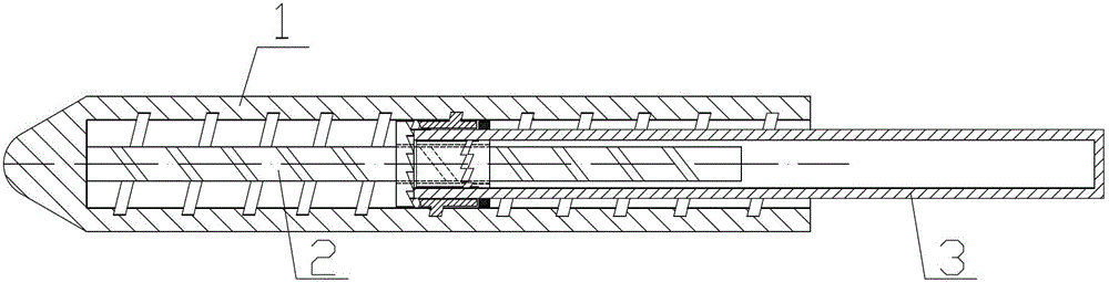
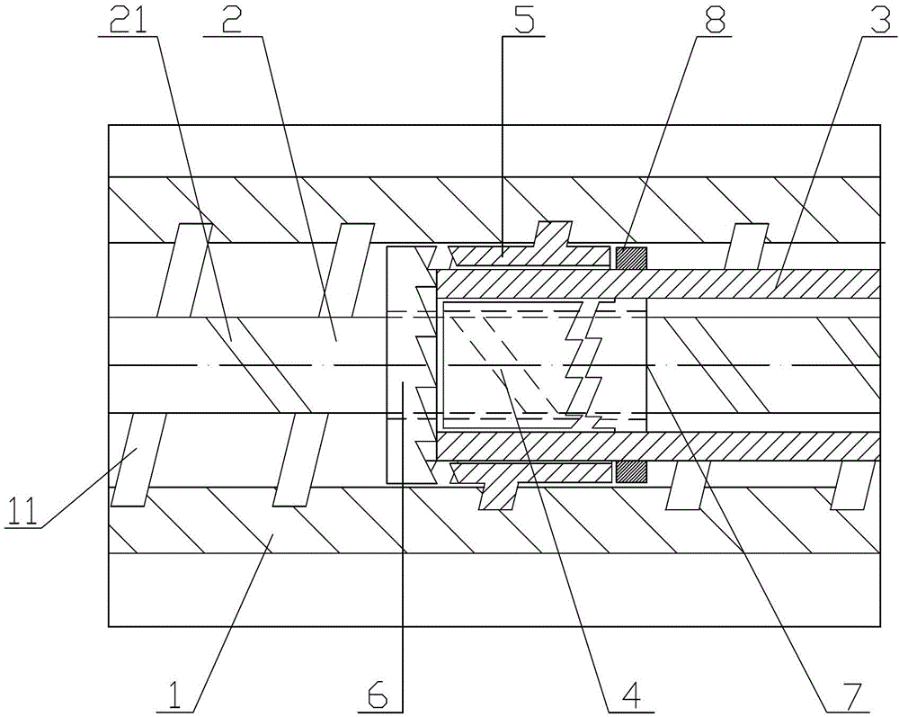
[0034] Such as figure 1 with figure 2 As shown, this embodiment discloses a mechanical device that converts a clutch-type reciprocating translation into continuous co-rotational motion. The device includes an externally threaded screw 1, an internally threaded screw 2, a rotating sleeve 3, and an internal rotating slider 4. Outer rotating slider 5, port closed ring 6, inner meshing ring 7, outer limit ring 8. The internally threaded screw 2 is installed inside the externally threaded screw 1 and arranged coaxially with the externally threaded screw 1. The left end of the externally threaded screw 1 is closed and used for connecting the driving device, and the right end is open and used for connecting the rotat...


PUM


Abstract

The invention discloses a mechanical device converting clutch type reciprocating horizontal motion into continuous rotary motion in the same direction. The device comprises an internal thread screw rod installed in an external thread screw rod and coaxial to the external thread screw rod in arrangement. One end of the external thread screw rod is closed and used for being connected with a driving device, and the other end of the external thread screw rod is opened and used for being connected with a rotary sleeve. An internal rotation sliding block, an external rotation sliding block, a port closing circular ring, an internal meshing circular ring and an external limiting circular ring are installed in one end of the rotary sleeve and are used for enabling the rotary sleeve to be connected between the external thread screw rod and the internal thread screw rod in a sleeved mode and to freely rotate in the space between the external thread screw rod and the internal thread screw rod, and the other end of the rotary sleeve is used for being connected with an output device. The mechanical device enables the reciprocating translational motion to be converted into the continuous rotary motion in same direction, thus inertia of rotation is fully used, conversion links are small, no dead points exist, transmission loss is small, and efficiency is remarkably improved; design is ingenious, the structure is compact, occupied space is small, therefore finished products can be designed to be large or small in size, requirements for application places are not high, and applicability is high.

Description

Technical field [0001] The invention relates to a transmission device, in particular to a mechanical device that converts reciprocating translational motion into rotary motion. Background technique [0002] At this stage, the mechanisms that convert reciprocating translation into rotary motion mainly include crank connecting rod mechanism, rack and pinion transmission mechanism, and ball screw pair. [0003] The crank connecting rod mechanism is a plane connecting rod mechanism that uses a crank and a slider to realize the mutual conversion of movement and rotation, and is a kind of connecting rod mechanism. The crank connecting rod mechanism can only approximate a given motion law or motion trajectory, and the design is relatively complicated, there are dead spots, self-locking is easy to form when starting, and the efficiency is low. [0004] The rack-and-pinion transmission mechanism converts the reciprocating linear motion of the rack into the rotary motion of the gear, which ha...

Claims


Application Information

Patent Timeline
Patent Type & Authority Patents(China)
IPC IPC(8): F16H25/12
Inventor 李大鸣李杨杨潘番赵明雨
Owner TIANJIN UNIV
Why Eureka
Try Eureka