Emergency lamp control method

A control method and technology for emergency lights, applied in the field of lighting, can solve the problems of short use time, use of lighting lamps, and provide lighting, and achieve the effect of increasing use time and long use time

Active Publication Date: 2015-04-15
NINGBO LEXING INDUCTOR ELECTRONIC CO LTD
View PDF11 Cites 0 Cited by
  • Summary
  • Abstract
  • Description
  • Claims
  • Application Information

AI Technical Summary

Problems solved by technology

[0002] At present, along with the gradual promotion of public disaster reduction and prevention, people have begun to install emergency lights at home in case they are needed from time to time, but the circuit structures of the emergency lights in the prior art are only suitable for separate installation and use, It can only be turned on when the power is off, and it cannot be used as an ordinary lighting that is directly on and off, which increases the cost of use for ordinary households, and thus makes emergency lights unable to be popularized; In the open state, the power of the battery can only keep the emergency light working for 1-2 hours, so the use time is short, and it cannot provide lighting in the event of a long-term power outage

Method used


Image

  • Emergency lamp control method

Examples


Embodiment Construction

[0010] The present invention will be further described below in conjunction with the accompanying drawings and specific embodiments.

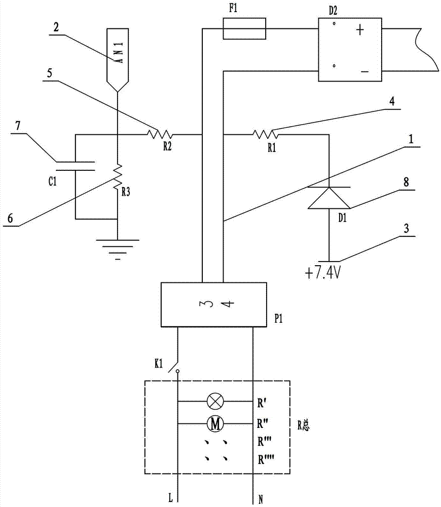
[0011] The circuit structure of a kind of emergency light as shown in Figure 1, it comprises input circuit 1, detection port 2 and battery 3 (also comprises other circuit structures of course, but because the invention point that does not relate to the invention of the present invention, so no longer here repeat, and not shown in the drawings), the input line 1 is electrically connected to the detection port 2, the input line 1 is provided with a switch signal detection circuit, and the switch signal detection circuit is connected to the detection port 2 and battery 3 are electrically connected.

[0012] The switch signal detection circuit includes a first resistor 4, a second resistor 5, a third resistor 6, a capacitor 7 and a diode 8, one end of the first resistor 4 is electrically connected to one pole of the input line 1, and the second Th...


PUM


Abstract

An emergency lamp circuit structure comprises an input line (1), a detection port (2) and a cell (3), wherein the input line (1) and the detection port (2) are electrically connected, the input line (1) is provided with a switch signal detection circuit, and the switch signal detection circuit is electrically connected with the detection port (2) and the cell (3). Compared with the prior art, the emergency lamp circuit structure and the emergency lamp control method have the following advantages: 1. when power is on, a switch can be used for switching on and switching off the emergency lamp directly so that the emergency lamp can be used as a conventional illumination lamp; and 2. when the power is off, the emergency lamp can be used for emergency illumination and at the same time can be controlled by the switch for direct switching-on and switching-off, so that when not needed for emergency illumination, the emergency lamp can be switched off through the switch and be prevented from continuously working in case of no illumination needs, thus the service life of the cell can be prolonged. Compared to a conventional emergency lamp in the prior art, the cell can be used for one to two years at a standby state by adopting the provided circuit and method.

Description

technical field [0001] The invention belongs to the technical field of lighting, and in particular relates to a circuit structure of an emergency light and a control method thereof. Background technique [0002] At present, along with the gradual promotion of public disaster reduction and prevention, people have begun to install emergency lights at home in case they are needed from time to time, but the circuit structures of the emergency lights in the prior art are only suitable for separate installation and use, It can only be turned on when the power is off, and it cannot be used as an ordinary lighting that is directly on and off, which increases the cost of use for ordinary households, and thus makes emergency lights unable to be popularized; In the open state, the power of the battery can only maintain the emergency light for 1 to 2 hours, so the use time is short, and it cannot provide lighting in the event of a long-term power outage. Contents of the invention [...

Claims


Application Information

Patent Timeline
Patent Type & Authority Patents(China)
IPC IPC(8): H05B37/02
Inventor 王荣庆
Owner NINGBO LEXING INDUCTOR ELECTRONIC CO LTD
Why Eureka
Try Eureka